Chapter: Mechanical : Computer Aided Design : Assembly of Parts
Important Questions and Answers: Assembly of Parts
ASSEMBLY OF PARTS
1. Define
Assembly modeling.
Assembly modeling is defined as a
technology and method used by computer-aided design and product visualization
computer software systems to handle multiple files that represent components
within a product. The components within an assembly are represented as solid or
surface models.
2. Write
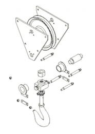
short note on Exploded view.
An exploded view consists of
series of steps. One can create steps by selecting and dragging parts in
graphical area.
Example – Exploded view of Assembly of Pulley block

3. List
Features of Bottom-up assembly approach.
•
Allows the designer to use part drawings that
already exist (off the shelf)
•
Provides the designer with more control over
individual parts
•
Multiple copies (instances) of parts can be
inserted into the assembly
4.
List Features of Top-down assembly approach.
•
The approach is ideal for large assemblies
consisting of thousands of parts.
•
The approach is used to deal with large designs
including multiple design teams.
•
It lends itself well to the conceptual design
phase
•
E.g. :
▫
Piping and fittings
▫
Welds
▫
Lock pins
5.
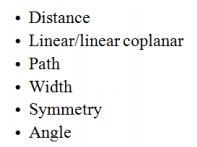
List advanced Mating conditions in assembling
modeling.

6. Applications
of Assembly Models Interference checking Visualization
•
Rendered
•
Exploded
•
Animation
•
Mechanism analysis
7.
Assembly sequence affects
•
difficulty of assembly steps
•
need for fixture
•
potential for parts damage during assembly and
part mating
•
ability to do in-process testing
•
occurrence of the need for reworking
•
time of assembly
•
assembly skill level
•
unit cost of assembly
8.
Interference fit
•
Fits is clearance fit
•
tight fits is interference fit
•
Coplanar: two normal vectors are parallel
•
‘Coplanar’ complements ‘against’
9.
Sketch the Precedence Diagram.
• Designed
to show all the possible assembly sequences of a product.
• Each
individual assembly operation is assigned a number.
• Diagram
is usually organized into columns
10. What are
the three terms used in limit system?
1. Tolerance: Deviation from a basic value
is defined as Tolerance. It can be obtained by taking the difference
between the maximum and minimum permissible limits.
2. Limits: Two extreme permissible sizes
between which the actual size is contained are defined as limits.
3. Deviation: The algebraic difference
between a size and its corresponding basic size. There are two types of
deviations: 1) Upper deviation 2) Lower deviation
11. Write
short note on Tolerances.
Due to human errors, machine settings, etc., it is
nearly impossible to manufacture an absolute dimension as specified by the
designer. Deviation in dimensions from the basic value always arises. This
deviation of dimensions from the basic value is known as Tolerance.
12. Define Clearance fit.
Clearance fit is defined as a
clearance between mating parts. In clearance fit, there is always a positive
clearance between the hole and shaft.
13. Why Transition fit occurs?
Transition fit may result in either
an interference or clearance, depending upon the actual values of the tolerance
of individual parts.
14. When Interference fit is obtained?
Interference fit is
obtained if the difference between the hole and shaft sizes is negative before assembly. Interference fit generally
ranges from minimum to maximum interference. The two extreme cases of
interference are as follows:
15. What is called
Minimum interference?
The magnitude of the difference
(negative) between the maximum size of the hole and the minimum size of the shaft in an interference fit before assembly.
Related Topics