Chapter: Mechanical : Computer Aided Design : Assembly of Parts
Assembly modeling
Assembly modeling
Assembly modeling is a technique applied
by CAD and product visualization software systems to utilize multiple files
that shows components within a product. The components within an assembly are
called as solid / surface models.
The designer usually
has approach to models that others are functioning on concurrently. For
example, different people may be creating one machine that has different
components. New parts are extra to an assembly model as they are generated.
Every designer has approach to the assembly model, during a work in progress,
and while working in their own components. The design development is noticeable
to everyone participated. Based on the system, it might be essential for the
users to obtain the most recent versions saved of every individual component to
update the assembly.
The personal data files
defining the 3D geometry of personal components are assembled together via a
number of sub assembly levels to generate an assembly explaining the complete
product. Every CAD methods support the bottom-up construction. A few systems,
through associative copying of geometry between components allow top-down
construction. Components can be situated within the assembly applying absolute
coordinate position methods.
Mating conditions are
defines of the relative location of mechanism between each other; for example
axis position of two holes or distance between two faces. The final place of
all objects based on these relationships is computing using a geometry
constraint engine built into the CAD package.
The significance of
assembly modeling in obtaining the full advantages of Product Life-cycle
Management has directed to ongoing benefits in this technology. These contain
the benefit of lightweight data structures that accept visualization of and
interaction with huge amounts of data related to product, interface between PDM
systems and active digital mock up method that combine the skill to visualize the
assembly mock up with the skill to design and redesign with measure, analyze
and simulate.
1. Assembly Concepts
When components are
additional to an assembly, parent and child relationships are created. These
relationships are displayed by graphically as an assembly tree. Parts are
parametrically connected by position constraints. These constraints have data
about how a part should be placed within the assembly hierarchy and how it
should respond if other components are edited.
Functioning within the
framework of an assembly is prepared easier by accepting to apply more commands
to other parts and sub-assemblies. These contain the Annotation Text, Inquire,
Point, Datum Plane and Pattern Component commands. Bigger assembly performance
is improved by removing unwanted redraws and improved display management while
zooming.
Assembly
models have additional data than simply the sum of their components. With
assembly modeling interference verifies between parts and assembly specific
data such as mass properties.
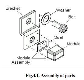
Fig.4.1.
Assembly of parts
2. Bottom up Assembly design
In a ‘bottom
up’assembly design, complex assemblies are divided into minor subassemblies and
parts. Every part is considered as individual part by one or more designers.
The parts can be archived in a library in one or more 3D Files. This is
the high effective way to generate and manage
complex assemblies.
Every part is included
into the active part making a component request and thus an assembly. The
component will be the child of the active part and then it will be the active
part. Hence an instance
of the actual part is applied; it revises
automatically if the archived part is edited by activating.
Bottom up Hierarchy:
The ‘bottom up’assembly
design hierarchy of the basic assembly is shown in figure 4.2. All the parts
exist prior to Part1. When Part1 is generated, it becomes the
active. It would utilize the menu
sequence to add Bracket and it becomes the
active part.
Insert
> Component
Or
Assembly
Design Tool Bar >
As
per example shown in figure 4.2., ‘Bracket’is a child of
Part1. The dashed line represents that
‘Bracket’exists in the 3D file
Parts Z3. The dotted line represents
that ‘Bracket’is inserted into Part-1.
After Bracket is added, Part1 is
redefined. Bolt and Washer are then added
the same process and Part-1 is reactivated
again.
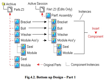
Fig.4.2.
Bottom up Design –Part 1
Module
of subassembly is added similar as ‘Bracket’,‘Bolt’,and
‘Washer’again becoming a
child of Part-1. But, because Module
Subassembly already has the two items Seal and Module, they
are added and continue as its children.
Sequence
of operations (Fig. 4.2.):
§ File-1
has
1 part.
§ Part-1
has
4 components.
§ Module
Subassembly has 2 components.
§ All
of the items are illustrations of the original parts that reside in the ZW3D
file Parts Z3.
§ If
File-1 is eliminated from the active assembly before it is saved and Part1
are removed. The original parts placed in the file Parts Z3 are not
changed.
§ If
File-1 is saved and Part1 is also saved.
§ If
File-1 is erased and Part1 is also erased.
3.Top down Assembly Design
In a ‘topdown’assembly design all parts
are classically designed by the similar person within a single part. 3D
assembly handles ‘top down’method by allowing to design and creation of
a component while work in the active part. Hence, the active part will be an
assembly part.
The part becomes a child of the active part and then
it will be the active part. The part, when generated, is an instance of a base
part which will be a root object located in the active file. Every part is
activated and modified as needed. The ‘top down’assembly design has its
benefits. If the project is terminated or to go in a different new direction,
removing the file will remove the part and all of its components.
Top down Hierarchy
The ‘top down’assembly
method is shown in a figure 4.3 and one of the components exist prior to Part-1.
When Part-1 is generated, it will be the active part. The following
command sequence to generate Bracket and create it the active part.
Assembly
Design Tool Bar >
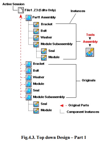
Fig.4.3.
Top down Design –Part 1
Bracket is
a child of Part-1. The dashed line illustrates that by default when
Bracket is generated; it is attached to File-1. The dotted
line illustrates that Bracket is attached into Part-1. When Bracket
is executed Part1 is reactivated. Bolt and Washer
are then generated using the similar process and Part-1 is reactivated
again.
Subassembly
Module is generated like the Bracket, Bolt, and
Washer again will be a child of Part1. But, Module
Subassembly remains active when seal is developed. Seal will be the
active part and by default also exists in File-1 but is inserted into Module
Subassembly hence it was active at the time of seal was created.
Subassembly Module is then reactivated and Module
is generated like
a
Seal.
Sequence
of operations (Fig 4.3):
· File-1
has 7.
· Part-1
contains 4 components, which are illustrations of the basic parts located in
File-1.
·
Subassembly Module contains 2 components
which are also illustrations of the basic parts located in File-1.
· If
File-1 is saved it has all of its original parts.
· If
File-1 is erased, it and all of its basic parts are erased.
Related Topics