Chapter: Mechanical : Computer Aided Design : Assembly of Parts
Interference of position and orientation
Interference of
position and orientation
Designers and manufacturers should check
jointly that a provided product can be assembled, without interference between
parts, before the product to be manufactured. Similarly, all the CAD tools
presently have the potential to directly analyze the possibility of a specified
assembly plan for a product.
An assessment of previous assembly
sequence and optimization research explains that most previous assembly
planners apply either feature-mating or interference-free techniques to find
assembly part interference interaction. In both feature-mating and
interference-free techniques focused upon the basic geometrical data and
restrictions for the designed product, which are generally contained in
connected CAD files.
When completely automate the procedure
of creating a professional assembly plan, geometrical information for CAD
models should be automatically taken from CAD files, analyzed for interference
relationships between components in the assembly, and then designed for
utilized the assembly analysis tools. Most of the previous assembly sequence
planners do not have the potential to complete the three tasks; they need users
to manually input part attributes or interference data, which is so
time-consuming.
Determining
Interference Relationships between Parts
In automated assembly
schemes, most parts are assembled along with the principal axis. Hence, to fine
interference between parts while assembly, the projected technique referred six
assembly directions along with the principal assembly axis: +x, -x,
+y, -y, +z, and -z. But, the method could be
improved, to think other assembly directions, as required. The projected system
uses projection of part coordinates onto planes in three principal axis (x,
y ,z) to find the obstruction between parts sliding along some of
the six principal assembly axis. The projections overlap between any two parts
in a specified axis direction shows a potential interference between the two
parts, when one of the two parts slides along the specified direction, with
respect to the other. Vertex coordinates for overlapped projections are then
evaluated to find if real collisions would happen between parts with overlapped
projections. The planned process stores the determined interference data for
allocated assembly direction in a group of interference free matrices, for
compatibility with previous planners of assembly.
The swept volume
interference and the multiple interference detection systems are appropriate
for three-dimensional interference determination between B-REP entities. But,
both techniques were developed for real-time interference detection between two
moving parts in a simulation environment. As a result, these two techniques are
expensive in computationally. For the assembly planning issue, actual collision
finding capacity along subjective relative motion vectors is not require.
Instead, a efficient computational technique is required for finding if two
parts will collide when they are assembled in a specified order along any one
of the six principle assembly axis.
Interference-free matrix
An interference-free
matrix shows interference between two components, when one component is moved,
in a given assembly direction, into an assembled location, with another
component already in an assembled location. Assembly actions that result in
interferences are denoted as ‘0’in the matrix, and assembly actions that do not
result in interferences are denoted as ‘1’in the matrix.
As
shown in figure 4.4., the interference-free matrix of an assembly having three
parts, for assembly movement sliding from infinity of negative toward infinity
of positive along the +x direction is as follows:
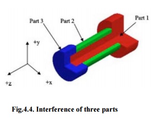
Fig.4.4.
Interference of three parts
Interference-free
matrix for sliding in the +x direction:
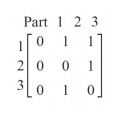
The row in the
Interference-free matrix indicate the components being shifted during a given
assembly operation, and the column indicate the parts that have previously been
assembled. Hence, since matrix element (2, 1) is equal to ‘0’,if Part-1 is
assembled initially, and after that Part-2 is assembled in the direction of +x,
Part-2 will collide with Part-1. Similarly, matrix element (1, 2) is equal to
‘1’,if Part-2 is assembled initially, and then Part-1 is assembled in the
direction of +x, Part-1 will not collide with Part-2. As a part cannot
be assembled after itself, all elements in the diagonal matrix are set to
‘0’.As a whole, six matrices are utilized to show interference relationships
between parts in the six principal axes. When robotically creating
interference-free matrices, the projected algorithm finds matrix elements row
by row. When two parts would interfere through assembly in a given direction,
the program inserts a ‘0’in the corresponding matrix position; or inserts as a
‘1’.
Related Topics