Chapter: Mechanical : Computer Aided Design : Assembly of Parts
Assembly modeling of Parts
ASSEMBLY MODELING OF PARTS
• Assembly modeling is a combination of two or more components using parametric relationships.
• Typically a designer would start with a base part
• Add other components to the base part using merge commands.
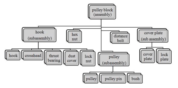
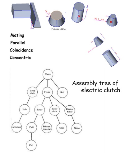
Assembly Tree
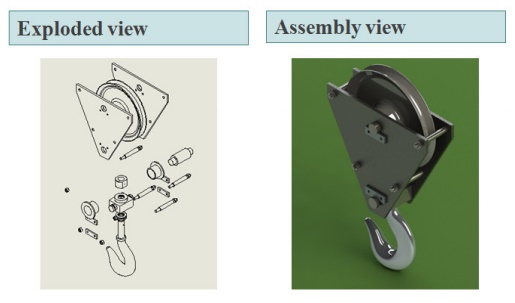
Exploded view
An exploded view consists of series of steps. One can create steps by selecting and dragging parts in graphical area.
Example - Assembly of Pulley block
Bottom-up assembly approach - :
• Allows the designer to use part drawings that already exist (off the shelf)
• Provides the designer w ith more control over individual parts
• Multiple copies (instan ces) of parts can be inserted into the assembly
Top-down assembly approach - :
• The approach is ideal for large assemblies consisting of thousands of parts.
• The approach is used to deal with large designs including multiple design teams.
• It lends itself well to t he conceptual design phase
• E.g. :
▫ Piping and fittings
▫ Welds
▫ Lock pins
Degrees of freedom -:
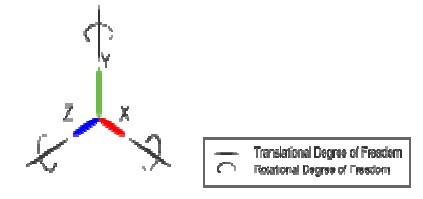
Translation – movement along X, Y, and Z axis
• Rotation – rotate about X, Y, and Z axis
Mating conditions -:
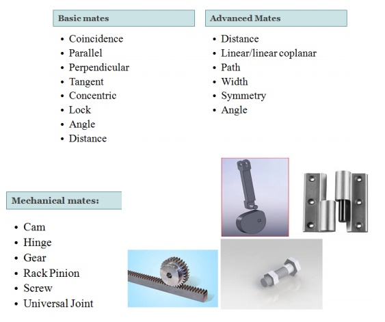
Assembly Constraints
• Constraints can be used to create permanent relationships between parts
• THEY use the same commands as 2D constraints
• Typical constraints:
– two faces meet
– axes coincident
– two faces parallel at fixed distance
Assembly sequence affects
• difficulty of assembly steps
• need for fixture
• potential for parts damage during assembly and part mating
• ability to do in-process testing
• occurrence of the need for reworking
• time of assembly
• assembly skill level
• unit cost of assembly
Related Topics