Chapter: Mechanical : Computer Aided Design : Assembly of Parts
Tolerance Analysis
Tolerance Analysis
Tolerance analysis is a
title to a different approaches applied in product design to know how
deficiencies in parts as they are manufactured, and in assemblies, influence
the ability of a product to meet customer needs. Tolerance analysis is a way of
accepting how basis of deviation in part dimensions and assembly constraints
distribute across parts and assemblies, and how that total deviation affects
the ability of a drawing to reach its design necessities within the process
capabilities of organizations and supply chains.
Tolerance openly
affects the cost and performance of products. In electrical machines, safety
needs that the power supply to be situated a minimum gap from adjacent
components, such as one more sheet-metal component, in order to remove
electrical short circuits. Tolerance analysis will describe whether the small
clearances specified will meet the safety requirement, assigned manufacturing
and assembly variability force on the minimum clearance.
1. Tolerance stack-up
Tolerance stack-up
computations show the collective effect of part tolerance with respect to an
assembly need. The tolerances ‘stacking wouldup’describe to adding tolerances
to obtain total part tolerance, then evaluating that to the existing gap in
order to see if the design will work suitably. This simple evaluation is also
defined as ‘worst case analyses’.Worst case analysis is suitable for definite
needs where failure would signify failure for a company. It is also needful and
suitable for problems that occupy a low number of parts. Worst case analysis is
always carried out in a single direction that is a 1-D analysis. If the
analysis has part dimensions that are not parallel to the assembly measurement
being defined, the stack-up approach must be edited since 2D variation such as
angles, or any variation that is not parallel with the 1-D direction, does not
influence the measurement of assembly with a 1-to-1 ratio.
The tolerance stacking
issue occurs in the perception of assemblies from interchangeable parts because
of the inability to create or join parts accurately according to nominal.
Either the applicable part dimension changes around various nominal value from
part by part or it is the act of assembly that directs to variation. For
example, as two parts are combined through matching holes pair there is not
only variation in the location of the holes relative to nominal centers on the
parts but also the slippage difference of matching holes relative to each other
when safe.
Thus there is the
opportunity that the assembly of such interacting parts will not move or won’t
come closer as planned. This can generally be judged by different assembly
criteria, say G1, G2,... Here we will be discussed with just one assembly
criterion, say G, which can be noted as a function of the part dimensions
L1,...,Ln. A example is shown in Figure 4.7., where n = 6 and is the clearance
gap of interest. It finds whether the stack of cogwheels will locate within the
case or not. Thus it is preferred to have G > 0, but for performance of
functional causes one may also require to limit G.
G
= L1(2 +−L3 + L4 + L5 + L6)
=
L1 −− L2L3− L45 −− L6
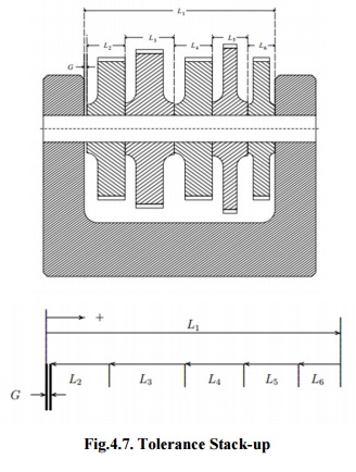
Fig.4.7.
Tolerance Stack-up
As per the example, the
required lengths ‘Li ‘may vary from the nominal lengths ‘λi’by a small value.
If there is higher variation in the ‘Li’there may well be important problems in
accepting G > 0. Thus it is sensible to limit these changes via tolerances.
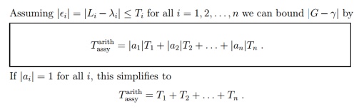
For similar tolerances, ‘Ti’,represent an ‘upper limit’on the absolute
variation between actual and nominal values of the i th detail part dimension,
it is means that |Li −λi|≤Ti. It is mostly in the interpretation of this last
inequality that the different methods of tolerance stacking vary.
The nominal value ‘γ’of
G is typically computed by replacing in equation L1 −L2 −L3 −L4 − L5 −L6, the
actual values of Li’sby the corresponding nominal values of λi,that is γ= λ1
−λ2 −λ3 −
λ4 λ5− λ−6.
2. Statistical method for tolerance
analysis (RSS) :
In RSS method,
tolerance stacking a significant new element is added to the assumptions, specifically
which the detail differences from nominal are random and independent from part
by part. It is expensive in the sense that it frequently commanded very close
tolerances. That all variations from nominal should dispose themselves in worst
case method to defer the higher assembly tolerance is a relatively unlikely
proposition. On the other hand, it had the advantage of assurance the resulting
assembly tolerance. Statistical tolerance in its typical form operates under
two basic hypotheses:
As
per Centered Normal Distribution, somewhat considering that the ‘Li’can occur
anywhere within the tolerance distribution [λi−Ti, λi + Ti], assume that the
‘Li’are normal random variables, that is change randomly according to a normal
distribution, centered on that similar interval and with a ±3σ distribute equal
to the span of that interval, hence 99.73% of all ‘Li’values occur within this
gap. As per the normal distribution is such that the ‘Li’fall with upper
frequency in the middle near ‘λi’and with low frequency closer the interval
endpoints. The match of the ±3σdistribution with the span of the detail
tolerance span is hypothetical to state that almost all parts will satisfy the
detail tolerance limits as shown in figure 4.8.
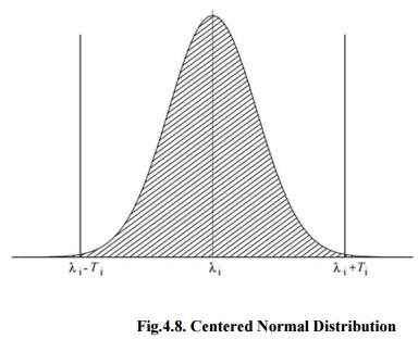
Fig.4.8.
Centered Normal Distribution
Statistical
tolerance stacking formula is given below:
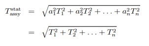
Where,
ai = ±1 for all i = 1,...,n.
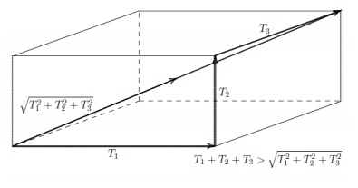
Fig.4.9.
RSS cube
Typically Tstat
assy is considerably smaller than T arith assy. For n=3, the scale
of this variation is simply visualized and valued by a rectangular box with
side lengths T1, T2 and T3. To obtain from one corner of the box to the
diagonally opposite corner, one can cross the gap T21 + T22 + T23 along that
diagonal and follow the three edges with lengths T1,
T2, and T3 for a total length T arith assy = T1 + T2 + T3 as shown in figure
4.9.
3. Second Order Tolerance Analysis
Due to the manufacturing methods changing for
various types of components, the distribution moments vary as well. RSS only
applies standard deviation and does not contain the upper moments of skewness
and kurtosis that describe the effects tool wear, form aging and other
classical manufacturing situations. Second Order Tolerance Analysis includes
all types of distribution moments as shown in figure 4.9
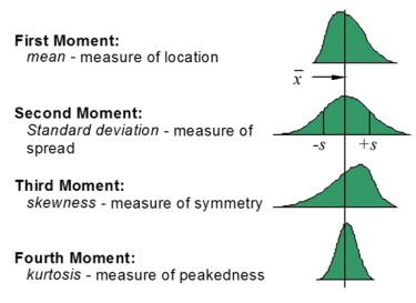
Fig.4.9.
Second order Tolerance Analysis
Second Order Tolerance Analysis is
required to find what output is going to be when the assembly function is not
linear. In classical mechanical engineering developments kinematic changes and
other assembly performances result in non-linear assembly operations. Second
order estimates are more complex so manual calculations are not suitable but
the computation is greatly improved and becomes feasible within tolerance
analysis software.
4.
Importance of Tolerance Analysis
With smaller product lifecycles, quicker
to market, and higher cost pressures, the uniqueness that distinguishes a
product from its competitors. Engineers are moving to the next order of
resolution in order to improve cycle time and quality and to reduce costs. They
are showing nearer at why they did not get the correct part and assembly
dimension values they needed from manufacturing and then are trying to optimize
the tolerances on the following version of the product. Optimization of
tolerance during design has a high impact on the output of manufacturing, and
better yields direct impact on product cost and quality. Tolerance Analysis
before trying to manufacture a product helps engineers avoid time taking
iterations later in the design cycle.
The electronics industry is attaining
customer satisfaction purposes via a physical shrinking of their components
while adding more capabilities. As electronic devices high densely packaged,
the significance increases to more accurately understanding the interaction of
manufacturing variation and tolerances in design. Similarly, in the aircraft,
automotive and medical device productions, liability costs are increasing while
environmental needs are being more forcefully forced such that companies
requires to understand high precisely what may reason a failure.
Advantages
of Tolerance Analysis
1.
Accurate part assembly.
2.
Elimination of assembly rework
3.
Improvement in assembly quality.
4.
Reduction of assembly cost.
5.
High customer satisfaction.
6. Effectiveness
of out-sourcing.
Limitations
of Tolerance Analysis
1.
Time consuming process.
2.
Skill require for complex assemblies.
Related Topics