Chapter: Microprocessor and Microcontroller : 8086 System Bus Structure
IO programming and Multiprocessor Systems
IO programming
On the
8086, all programmed communications with the I/O ports is done by the IN and
OUT instructions defined in Fig. 6-2.
ü IN and OUT instructions
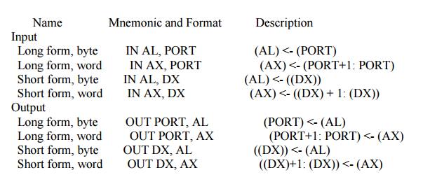
Note:
PORT is a constant ranging from 0 to 255
Flags: No
flags are affected
Addressing
modes: Operands are limited as indicated above.
If the
second operand is DX, then there is only one byte in the instruction and the
contents of DX are used as the port address. Unlike memory addressing, the
contents of DX are not modified by any segment register. This allows variable
access to I/O ports in the range 0 to 64K. The machine language code for the IN
instruction is:
Although
AL or AX is implied as the first operand in an IN instruction, either AL or AX
must be specified so that the assembler can determine the W-bit.
Similar
comments apply to the OUT instruction except that for it the port address is
the destination and is therefore indicated by the first operand, and the second
operand is either AL or AX. Its machine code is:
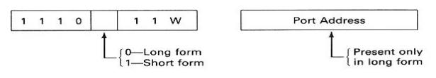
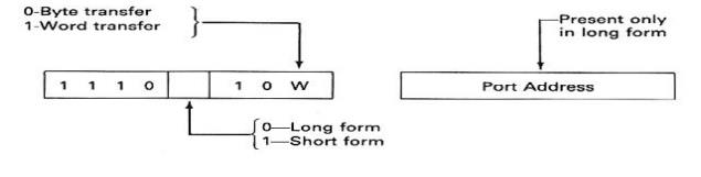
Note that
if the long form of the IN or OUT instruction is used the port address must be
in the range 0000 to 00FF, but for the short form it can be any address in the
range 0000 to FFFF (i.e. any address in the I/O address space). Neither IN nor
OUT affects the flags.
The IN
instruction may be used to input data from a data buffer register or the status
from a status register. The instructions
IN AX, 28H
MOV
DATA_WORD, AX
would
move the word in the ports whose address are 0028 and 0029 to the memory
location DATA_WORD.
Introduction to Multiprogramming
In order
to adapt to as many situations as possible both the 8086 and 8088 have been
given two modes of operation, the minimum mode and the maximum mode. The
minimum mode is used for a small system with a single processor, a system in
which the 8086/8088 generates all the necessary bus control signals directly
(thereby minimizing the required bus control logic). The maximum mode is for
medium-size to large systems, which often include two or more processors.
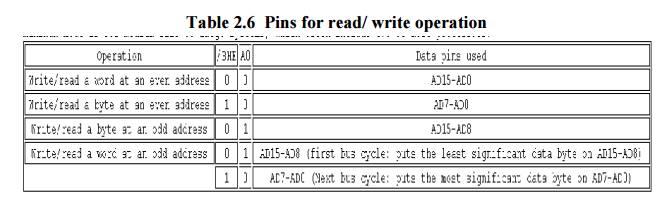
System Bus structure
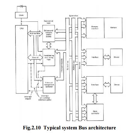
Table 2.6 Pins for read/ write operation
Multiprocessor
Systems refer to the use of multiple processors that execute instructions
simultaneously and communicate using mailboxes and semaphores
Maximum
mode of 8086 is designed to implement 3 basic multiprocessor configurations:
1. Coprocessor
(8087)
2. Closely
coupled (dedicated I/O processor: 8089)
3.
Loosely coupled (Multi bus)
Coprocessors
and closely coupled configurations are similar - both the CPU and the external processor
share:
Memory
I/O
system
Bus &
bus control logic
Clock
generator
Related Topics