Ideal characteristics, Principle, Operation - Frequency to Voltage (F-V) and voltage to frequency convertors (V-F) | Linear Integrated Circuits : Waveform Generators and Special Function ICs
Chapter: Linear Integrated Circuits : Waveform Generators and Special Function ICs
Frequency to Voltage (F-V) and voltage to frequency convertors (V-F)
Frequency
to Voltage (F-V) and voltage to frequency convertors (V-F)
Frequency to Voltage convertors (F-V)
┬Ę
F-V
convertors applications: Tachometer in motor speed control Rotational speed
measurement.
┬Ę
Two
types of it: Pulse integrating Phase locked loop
┬Ę
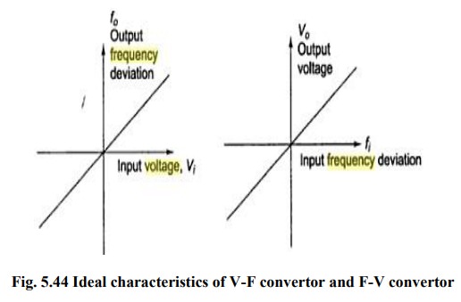
F-V
convertor produces an output voltage whose amplitude is a function of input
signal frequency.
┬Ę
V0=kf
fi kf is sensitivity of F-V
convertor
┬Ę
It
is basically a FM discriminator.
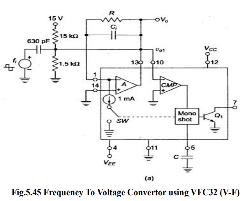
Input
frequency is applied to comparator A.
Resistor
R acts as feedback element.
Capacitor
Ci enables charge-balancing,
High
pass network conditions input signal
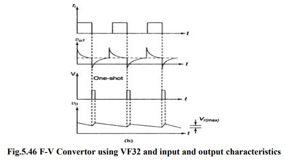
For
negative spike of V 01, comparator COMP triggers one shot multivibrator with
threshold 7.5V The output of multivibrator closes the switch SW, for a time TH,
this causes voltage Vo to build up and inject thru R and this continues until
current out of summing input of opamp is equal to that injected by Vo through R
continuously.
Vo=10-3
*TH *R*fi as TH =7.5 C /1X10-3
Ripple
Voltage, Vr(max) =7.5 C /Ci
Voltage to frequency convertor
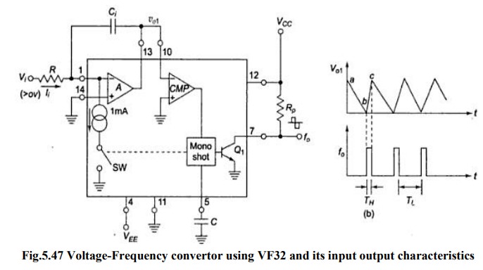
Principle: Charge balancing technique-the
process of charging and discharging results in frequency proportional to input signal F0= k Vi
Operation: Op-amp A converts input Vi to current Ii = Vi/R into summing
junction.
When
switch SW is open the current flows into capacitor Ci and charges it, and node
voltage Vo1 produce ramp down.
When
V01 =0 CMP triggers and sends a triggering signal to one shot
multivibrator that closes the switch SW and turns transistor Q ON for time TH.
The threshold of mono shot = 7.5 V and TH= 7.5 C/10-3
During
TH , V01 ramps
upward by amount ŌłåV01=(1mA-Ii) TH /Ci
Time
duration TL for vo1 to return to 0 is TL =
CŌłåV01/Ii
TL+TH
= 1mA TH /Ii = T
F0=Vi/7.5
RC
Related Topics