Chapter: Electronic Circuits : Biasing of Discrete BJT and MOSFET
Fixed Bias (Base Resistor Bias)
Fixed Bias (Base Resistor Bias)
The
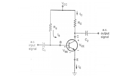
Figure shows the fixed bias circuit. It is the simplest d.c. bias
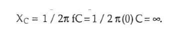
configuration. For the d.c. analysis we can replace capacitor with an open
circuit because the reactance of a capacitor for d.c. is
In the base circuit,
Apply
KVL, we get
VCC
= IBRB + VBE
Therefore,
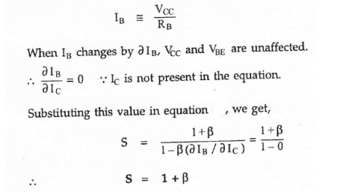
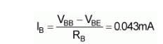
IB
= (VCC - VBE)/RB
For a
given transistor, VBE does not vary significantly during use. As VCC
is of fixed value, on selection of RB, the base current IB
is fixed. Therefore this type is called fixed
bias type of circuit.
In the Collector circuit
Apply
KVL, we get
VCC
= ICRC + VCE
Therefore,
VCE
= VCC - ICRC
The
common-emitter current gain of a transistor is an important parameter in
circuit design, and is specified on the data sheet for a particular transistor.
It is denoted as β.
IC
= βIB
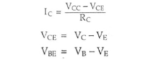
In this
circuit VE =0

Stability
factor S for Fixed bias circuit
Stability factor S
Merits:
·
It is simple to shift the operating point anywhere
in the active region by merely changing the base resistor (RB).
·
A very small number of components are required.
Demerits:
·
The collector current does not remain constant with
variation in temperature or power supply voltage. Therefore the operating point
is unstable.
·
Changes in Vbe will change IB
and thus cause RE to change. This in turn will alter the gain of the
stage.
·
When the transistor is replaced with another one,
considerable change in the value of β can be expected. Due to this change the
operating point will shift.
·
For small-signal transistors (e.g., not power
transistors) with relatively high values of β (i.e., between 100 and 200), this
configuration will be prone to thermal runaway. In particular, the stability
factor, which is a measure of the change in collector current with changes in
reverse saturation current, is approximately β+1. To ensure absolute stability
of the amplifier, a stability factor of less than 25 is preferred, and so
small-signal transistors have large stability factors.
Usage:
Due to
the above inherent drawbacks, fixed bias is rarely used in linear circuits
(i.e., those circuits which use the transistor as a current source). Instead,
it is often used in circuits where transistor is used as a switch. However, one
application of fixed bias is to achieve crude automatic gain control in the
transistor by feeding the base resistor from a DC signal derived from the AC
output of a later stage.
Problems
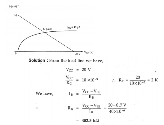
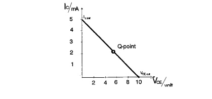
1. Design
the fixed bias circuit from the load line given in the figure.
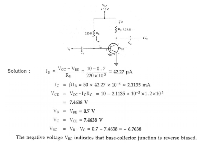
2. For
the circuit shown in figure. Calculate IB,IC,VCE,VB,VC
and VBC. Assume VBE= 0.7V and β=50.
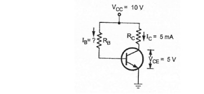
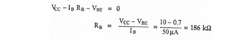
3. Design a fixed biased circuit using a
silicon transistor having β value of 100. Vcc is 10 V and dc bias conditions
are to be VCE = 5 V and IC = 5 mA,
Solution
Applying
KVL to collector circuit,
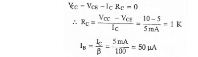
Applying
KVL to base circuit,
4. Calculate
the operating point (Q-point)
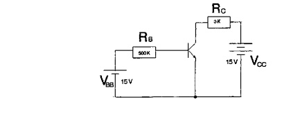
Base
biased CE connection

IC
= βdc * IB = 100 * 29µA = 2.9 mA
VCE
= VCC - (IC * RC) = 15V - (2.9 mA * 3KΩ) =
6.3V
By
plotting IC (2.9 mA) and VCE (6.3V), we get the operation
point ----> Q-point (quiescent point).
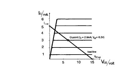
Collector
curve with load line and Q – point
5. Draw
the load line and Q-point.
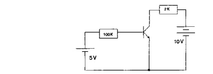
base
biased CE connection, β=50
Solution:
IC
= IB * β = 2.15 mA
VCE
= VCC - (RC * IC)= 5.7V
` VCE
(cut) = VCC = 3.0V
Related Topics