Chapter: Electronic Circuits : Biasing of Discrete BJT and MOSFET
Diode and Thermistor Compensation technique
Compensation technique:
It refers to the use of temperature sensitive devices such as diodes, transistors, thermistors which provide compensating voltage and current to maintain Q point stable.
1. Diode Compensation Techniques
Compensation for VBE:
a) Diode in Emitter Circuit
Diagram
shows the voltage divider bias with bias compensation technique.Here, separate
supply VDD is used to keep diode in forward If biased condition. If
the diode used in the circuit is of same material and type as the transistor,
the voltage across the diode will have the same temperature coefficient as the
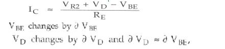
base to emitter voltage VBE . So when VBE changes by ∂ VBE with change in
temperature, VD changes by VD and ∂ VD~=~∂ VBE,
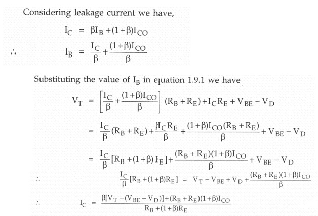
the changes tend to cancel each other. Apply*g KVL to the base circuit of Fig.
,we have
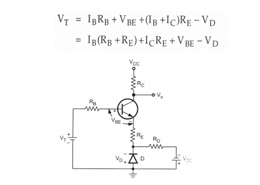
Figure: Stabilization by means of voltage divider bias and diode Compensation Technique
As VD tracks VBE with respect to temperature it is clear that IC will be insensitive to variations in VBE .
Diode in voltage divider circuit
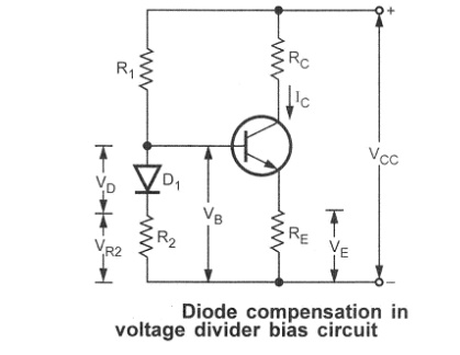
Diode is
connected in series with resistance R2 in the voltage divider
circuit and it is forward biased condition.
For
voltage divider bias,
When VBE
changes with temperature, IC also changes
To cancel
the changes in IC , one diode is used in the circuit for
compensation
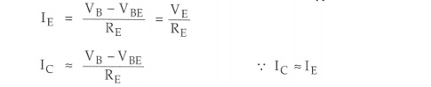
The
voltage at the base VB is give as

Substituting this value in equation IC,
we get,
The
changes cancel each other , so the collector current is given as
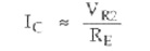
The
changes in VBE. Due to temperature are compensated by changes in the
diode voltage which keeps IC stable at Q point.
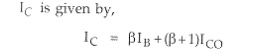
Compensation for ICO
*
In germanium transistor changes in ICO
with temperature plays an important role collector current stability
*
The diode is kept at reverse bias condition ,so
only leakage current flows
*
Io
increases then ICO also increases
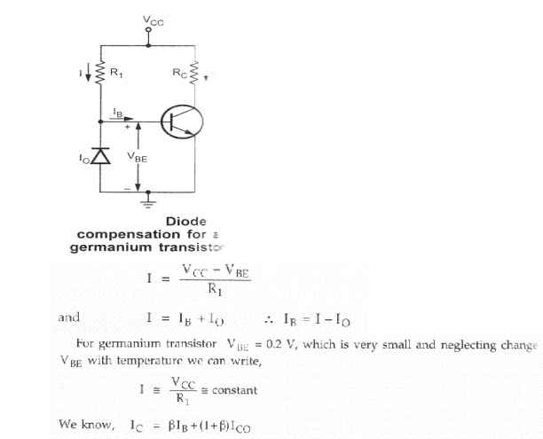
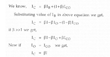
As I is
constant , IC also remains constant. We can say that changes by ICO
with temperature are compensated by diode and collector current remains
constant
2. Thermistor Compensation
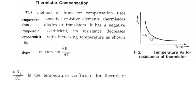
With
increase of temperature ,RT decreases. Hence the voltage drop across
it also decreases. That is VBE decreases which reduces IB
.this will offset the increased collector current with temperature.
The
equation shows if there is increase in ICO and decrease in IB
keeps IC almost constant.
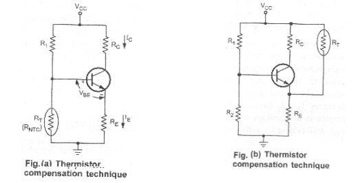
Fig (b)
shows another thermistor compensation technique . Here, thermistor is connected
between emitter and Vcc to minimize the increase in collector current due to
changes in ICO, VBE, or beta with temperature .IC increases with
temperature and RT decreases with increase in temperature.
Therefore, current flowing through RE increases, which increases the voltage drop
across it. E - B junction is forward biased. But due to increase in voltage
drop across RE, emitter is made more positive, which reduces the
forward bias voltage VBE. Hence, bias current reduces.
As Ico
increases with temperature, IB decreases and hence. IC remains
constant
Sensistor Compensation technique
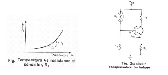
This
method of transistor compensation uses temperature sensitive resistive element,
sensistors rather than diodes or transistors. It has a positive temperature
coefficient, its resistance increases exponentially with increasing temperature
as shown in the Fig
Slope of
this curve = 
is the
temperature coefficient for thermistor and the slope is positive So we can say
that sensistor has positive temperature coefficient of resistance (PTC).
Fig.
shows sensistor compensation R1 is replaced by sensistor RT
in self bias circuit. Now, RT and R2 resistors of the
potential divider. As temperature increases, RT increases which decreases the
current flowing through it. Hence current through R2 decreases which reduces
the voltages drop across it. Voltage drop across R2 is the voltage between base
and ground. So VBE reduces which decreases 16. It means, when ICBO
increases with increase in temperature, IB reduces due to reduction
in VBE, maintaining IC fairly constant.
Related Topics