Chapter: 12th Physics : UNIT 10b : Communication Systems
Elements of an Electronic Communication System
THE ELEMENTS OF AN ELECTRONIC COMMUNICATION SYSTEM
Electronics plays a major role in communication. Electronic communication is nothing but the transmission of sound, text, pictures, or data through a medium. Long distance transmission uses free space as a medium. This section provides sufficient information on how voice signal is transmitted by a transmitter through space and received by the receiver at the receiving end.
Elements of an electronic communication system
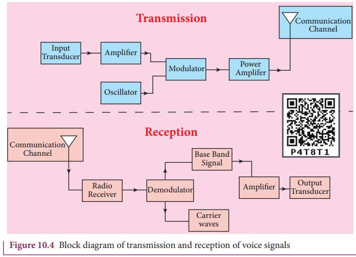
The elements of the basic communication system are explained with the block diagram shown in Figure 10.4.
1. Information (Baseband or input signal)
Information can be in the form of speech, music, pictures, or computer data.
This information is given as input to the input transducer.
2. Input transducer
A transducer is a device that converts variations in a physical quantity (pressure, temperature, sound) into an equivalent electrical signal or vice versa. In communication system, the transducer converts the information which is in the form of sound, music, pictures or computer data into corresponding electrical signals. The electrical equivalent of the original information is called the baseband signal. The best example for the transducer is the microphone that converts sound energy into electrical energy.
3. Transmitter
It feeds the electrical signal from the transducer to the communication channel. It consists of circuits such as amplifier, oscillator, modulator and power amplifier. The transmitter is located at the broadcasting station.
Amplifier: The transducer output is very weak and is amplified by the amplifier. Oscillator: Itgenerates high-frequency carrier wave (a sinusoidal wave) for long distance transmission into space. As the energy of a wave is proportional to its frequency, the carrier wave has very high energy.
Modulator: It superimposes the baseband signal onto the carrier signal and generates the modulated signal.
Power amplifier: It increases the power level of the electrical signal in order to cover a large distance.
4. Transmitting antenna
It radiates the radio signal into space in all directions. It travels in the form of electromagnetic waves with the velocity of light (3 × 10⁸ m s–1).
5. Communication channel
Communication channel is used to carry the electrical signal from transmitter to receiver with less noise or distortion. The communication medium is basically of two types: wireline communication and wireless communication.
Wireline communication (point to point communication) uses mediums like wires, cables and optical fibers. These systems cannot be used for long distance transmission as they are connected physically. Examples are telephone, intercom and cable TV.
Wireless communication uses free space as a communication medium. The signals are transmitted in the form of electromagnetic waves withthe helpof a transmitting antenna. Hence wireless communication is used for long distance transmission. Examples are mobile, radio or TV broadcasting and satellite communication.
6. Noise
It is the undesirable electrical signal that interferes with the transmitted signal. Noise attenuates or reduces the quality of the transmitted signal. It may be man-made (automobiles, welding machines, electric motors etc.) or natural (lightning, radiation from sun and stars and environmental effects). Noise cannot be completely eliminated. However, it can be reduced using various techniques.
7. Receiver
The signals that are transmitted through the communication medium are received by a receiving antenna which converts em waves into RF signals and are fed into the receiver. The receiver consists of electronic circuits like demodulator, amplifier, detector etc. The demodulator extracts the baseband signal from the modulated signal. Then the baseband signal is detected and amplified using amplifiers. Finally, it is fed to the output transducer.
8. Repeaters
Repeaters are used to increase the range or distance through which the signals are sent. It is a combination of transmitter and receiver. The signals are received, amplified and retransmitted with a carrier signal of different frequency to the destination. The best example is the communication satellite in space.
9. Output transducer
It converts the electrical signal back to its original form such as sound, music, pictures or data. Examples of output transducers are loudspeakers, picture tubes, computer monitor, etc.
Related Topics