Electricity | Chapter 5 | 8th Science - Electric Circuits | 8th Science : Chapter 5 : Electricity
Chapter: 8th Science : Chapter 5 : Electricity
Electric Circuits
Electric Circuits
We saw that when two oppositely charged
spheres are connected by a metal wire, electrons flow from the sphere which is
at lower potential to the sphere at higher potential. Similarly, if two
terminals of a battery which are at different potential are connected by a
metallic wire, electrons will flow from negative terminal to positive terminal.
The path through which electrons flow from one terminal to another terminal of
the source, is called electric circuit.
A simple circuit consists of four
elements: a source of electricity (battery), a path or conductor through which
electricity flows (wire), a switch to control the circuit and an electrical
resistor (lamp) which is any device that requires electricity to operate.
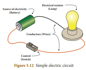
The above figure shows a simple
circuit containing a battery, two wires, key and an electric bulb. The source
can be a battery or the electric outlet in your room. The electrical resistor
refers to the device that consumes the energy. Control (key) is the mechanism
that is used to start, stop and regulate the electric current. When the key is
on, electrons from the battery flow through the circuit from the negative
terminal through the wire conductor, then through the bulb and finally back to
the positive terminal. The light glows when current is flowing through its
filament. There are two basic ways in which we can connect these components.
They are: series and parallel.
The electric eel is a
species of fish which can give electric shocks of upto six hundred fifty watts
of electricity. But if the eel repeatedlyshocks, its electric organs become
completely discharged. Then a person can touch it without being shocked.

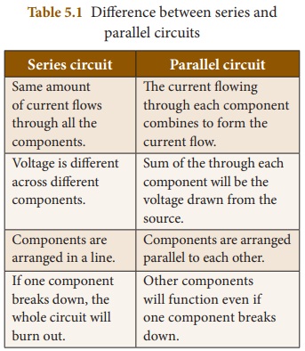
1. Series Circuit
A series circuit is one that has
more than one resistor (bulb) but only one path through which the electrons can
travel. From one end of the battery the electrons move along one path with no
branches through the resistors (bulbs) to the other end of the cell. All the
components in a series circuit are connected end to end. So, current through
the circuit remains same throughout the circuit. But, the voltage gets divided
across the bulbs in the circuit. In the following series circuit two bulbs are
used as resistors.
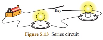
In this series circuit, charges
(electrons) from the battery have only one path to travel. Here battery, key
and two bulbs are connected in series. Charges flow from the battery to each
bulb, one at a time, in the order they are wired to the circuit. If one bulb in
the circuit is unscrewed, the current flow to another bulb would be interrupted.
We put serial lights during festivals. If the lights are in a series circuit,
one burned out bulb will keep all the lights off. If the number of bulbs in a
circuit with a battery increases, the light will be dimmer because many
resistors are acting on the same power from the battery.
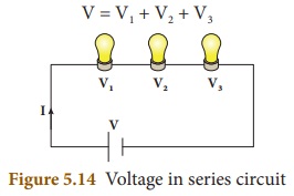
We saw that in series circuit same
current travels through every resistance and the voltage will be different
across each resistance. Let us consider three bulbs connected in series. Let I
be the current through the circuit and V1, V2, V3
be the voltage across each bulb. The supply voltage V is the total of the
individual voltage drops across the resistances (bulbs).
V=V1+V2+V3
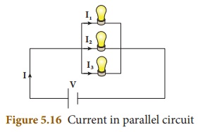
2. Parallel Circuit
In a parallel circuit, there is more
than one resistor (bulb) and they are arranged on many paths. This means
charges (electrons) can travel from one end of the cell through many branches
to the other end of the cell. Here, voltage across the resistors (bulbs) remains
the same but the current flowing through the circuit gets divided across each
resistor.
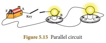
In the above diagram, current can
flow in two paths: ABEFA and ABCDEFA. Here, it is clear that electricity from
the cell can take either path ABEFA or path ABCDEFA to return to the cell. From
the diagram you will notice that even when one resistor (bulb) burns out, the
other bulbs will work because the electricity is not flowing through only one
path. All the light bulbs in our homes are connected in parallel circuit. If
one bulb burns out, the other bulbs in the rooms will still work. The bulbs in
a parallel circuit do not dim out as in series circuits. This is because the
voltage across one branch is the same as the voltage across all other branches.
Let us consider three bulbs
connected in series. Let V be the voltage across the bulbs and I1, I2,
I3 be the current across each bulb. The current I from the battery
is the total of the individual current flowing through the resistances (bulbs).
I = I1+I2+I3
Related Topics