Chapter: physics 11th 12th standard school college definition answer assignment examination viva question
Diffraction grating explanation with Theory
Diffraction grating
An arrangement consisting of a large number of equidistant parallel narrow slits of equal width separated by equal opaque portions is known as a diffraction grating.
The plane transmission grating is a plane sheet of transparent material on which opaque rulings are made with a fine diamond pointer. The modern commercial form of grating contains about 6000 lines per centimetre.
The rulings act as obstacles having a definite width ‘b’ and the transparent space between the rulings act as slit of width ‘a’. The combined width of a ruling and a slit is called grating element (e). Points on successive slits separated by a distance equal to the grating element are called corresponding points.
Theory
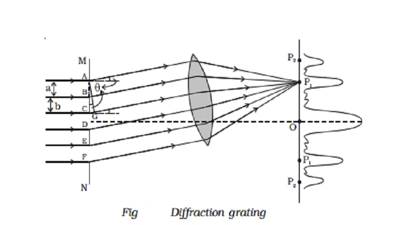
MN represents the section of a plane transmission grating. AB, CD, EF … are the successive slits of equal width a and BC, DE … be the rulings of equal width b (Fig. 5.21). Let e = a + b.
Let a plane wave front of monochromatic light of wave length λ be incident normally on the grating. According to Huygen’s principle, the points in the slit AB, CD … etc act as a source of secondary wavelets which spread in all directions on the other side of the grating.
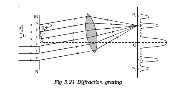
Let us consider the secondary diffracted wavelets, which makes an angle θ with the normal to the grating.
The path difference between the wavelets from one pair of corresponding points A and C is CG = (a + b) sin θ. It will be seen that the path difference between waves from any pair of corresponding points is also (a + b) sin θ
The point P1 will be bright, when
(a + b) sin θ = m λ where m = 0, 1, 2, 3
In the undiffracted position θ = 0 and hence sin θ = 0.
(a + b) sin θ = 0, satisfies the condition for brightness for m = 0. Hence the wavelets proceeding in the direction of the incident rays will produce maximum intensity at the centre O of the screen. This is called zero order maximum or central maximum.
If (a + b) sin θ1 = λ, the diffracted wavelets inclined at an angle θ1 to the incident direction, reinforce and the first order maximum is obtained.
Similarly, for second order maximum, (a + b) sin θ2 = 2λ
On either side of central maxima different orders of secondary maxima are formed at the point P1, P2.
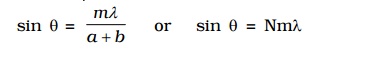
In general, (a + b) sin θ = m λ is the condition for maximum intensity, where m is an integer, the order of the maximum intensity.
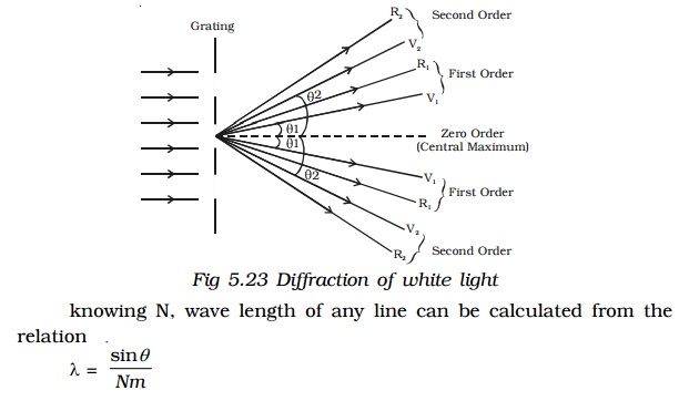
When white light is used, the diffraction pattern consists of a white central maximum and on both sides continuous coloured images are formed.
where N = 1/a+b , gives the number of grating element or number of lines per unit width of the grating.
In the undiffracted position, θ = 0 and hence sin θ = 0. Therefore sin θ = Nmλ is satisfied for m= 0 for all values of λ. Hence, at O all the wavelengths reinforce each other producing maximum intensity for all wave lengths. Hence an undispersed white image is obtained.
As θ increases, (a + b) sin θ first passes through λ/2 values for all colours from violet to red and hence darkness results. As θ further increases, (a + b) sin θ passes through λ values of all colours resulting in the formation of bright images producing a spectrum from violet to red. These spectra are formed on either side of white, the central maximum.
Experiment to determine the wavelength of monochromatic light using a plane transmission grating.
The wavelength of a spectral line can be very accurately determined with the help of a diffraction grating and spectrometer.
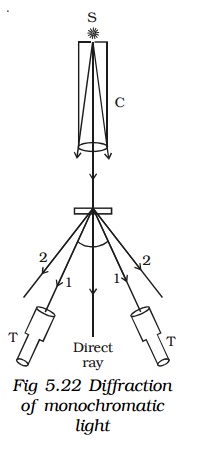
Initially all the preliminary adjustments of the spectrometer are made. The slit of collimator is illuminated by a monochromatic light, whose wavelength is to be determined. The telescope is brought in line with collimator to view the direct image. The given plane transmission grating is then mounted on the prism table with its plane is perpendicular to the incident beam of light coming from the collimator. The telescope is slowly turned to one side until the first order diffraction image coincides with the vertical cross wire of the eye piece. The reading of the position of the telescope is noted (Fig. 5.22).
Similarly the first order diffraction image on the other side, is made to coincide with the vertical cross wire and corresponding reading is noted. The difference between two positions gives 2θ. Half of its value gives θ, the diffraction angle for first order maximum. The wavelength of light is calculated from the equation λ = sin θ/ Nm. Here N is the number of rulings per metre in the grating.
Determination of wavelengths of spectral lines of white light
Monochromatic light is now replaced by the given source of white light. The source emits radiations of different wavelengths, then the beam gets dispersed by grating and a spectrum of constituent wavelengths is obtained as shown in Fig 5.23.
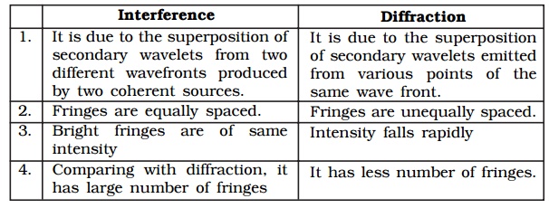
Difference between interference and diffraction
Related Topics