Operational Amplifiers - Constant current source (Current Mirror) | Linear Integrated Circuits : Basics of Operational Amplifiers
Chapter: Linear Integrated Circuits : Basics of Operational Amplifiers
Constant current source (Current Mirror)
Constant
current source (Current Mirror):
A
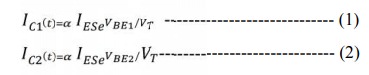
constant current source makes use of the fact that for a transistor in the
active mode of operation, the collector current is relatively independent of
the collector voltage. In the basic circuit shown in fig 1 and collector
characteristics of a CE Transistor as in fig.2
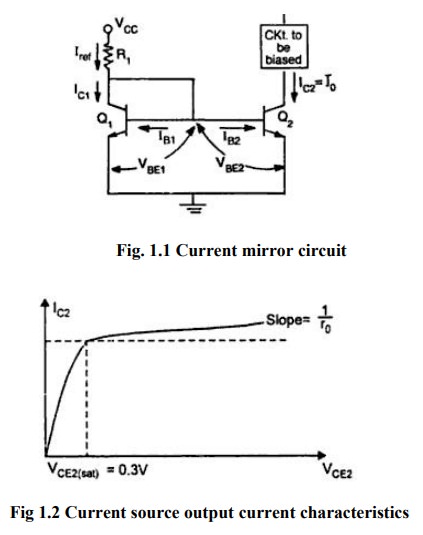
Transistors
Q1&Q2 are matched as the circuit is fabricated using
IC technology. Base and emitter of Q1& Q2 are tied
together and thus have the same VBE. In addition, transistor Q1 is
connected as a diode by shorting its collector to base. The input current Iref
flows through the diode connected transistor Q1 and thus establishes
a voltage across Q1. This voltage in turn appears between the base
and emitter of Q2 .Since Q2 is identical to Q1,
the emitter current of Q2 will be equal to emitter current of Q1
which is approximately equal to Iref. As long as Q2 is maintained in
the active region ,its collector current IC2=Io will be
approximately equal to Iref . Since the output current Io is a
reflection or mirror of the reference current Iref, the circuit is
often referred to as a current mirror.
Analysis:
The
collector current IC1 and IC2
for the transistor Q1 and Q2 can be approximately expressed
as
Where
IES is reverse saturation current in emitter junction and VT is
temperature equivalent of voltage.
From
equation (1) & (2)
Since
VBE1=VBE2 we obtain IC2=IC1=I\C=IO
Also
since both the transistors are identical, IC1= IC2
KCL
at the collector of Q1 gives
Iref=
IC1+IB1+IB2
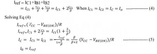
From
Eq.5 for β/ [β +1] >>1, is almost unity and the output current I0 is
equal to the reference current, ref which for a given R1 is constant.
Typically Io varies by about 3% for 50 ≤ β ≤200.
The
circuit however operates as a constant current source as long as Q2
remains in the active region.
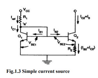
Widlar current source:
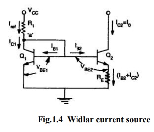
Widlar
current source which is particularly suitable for low value of currents. The
circuit differs from the basic current mirror only in the resistance RE
that is included in the emitter lead of Q2. It can be seen that due
to RE the base-emitter voltage VBE2 is less than VBE1 and
consequently current Io is smaller than IC1
The
ratio of collector currents IC1&IC2 using
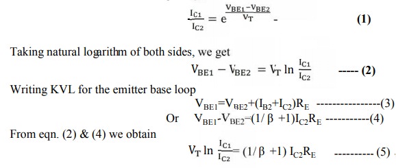
A
relation between IC1 and the reference current Iref is
obtained by writing KCL at the collector point of Q1
Iref
= IC1 + IB1 + IB2
Iref
= IC1 + IC1/β + IC2/β
Neglecting
IC2/β,
Iref
= IC1 (1 + 1/β)
Iref
= [ Vcc - VBE ] /R1
When
β>> 1, IC1 = Iref
Wilson current source:
The
Wilson current source shown in figure
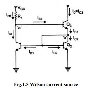
It
provides an output current I0 which is very nearly equal to Vref and also
exhibits a very high output resistance.
Analysis
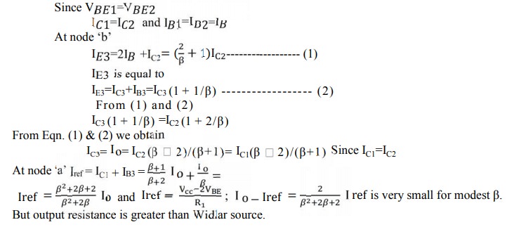
But
output resistance is greater than Widlar source.
Related Topics