Chapter: Basic Electrical and Electronics Engineering : Digital Electronics
synchronous and counter
synchronous
(1)
Pertaining to two or more processes that depend upon the occurrence of
specific events such as common timing signals. (2) Occurring with a regular or
predictable time relationship.
counter (1) A
functional unit with a finite number of states each of which represents a
number that can be, upon receipt of an appropriate signal, increased by unity
or by a given constant. This device is usually capable of bringing the
represented number to a specified value; for example zero.
So a
"synchronous counter" is actually a functional unit with a certain
number of states, each representing a number which can be increaced or
decreased upon receiving an appropriate signal (e.g. a rising edge pulse), and
is usually used to count to, or count down to zero from, a specified number N.
.Basically,
any sequential circuit that goes through a prescribed sequence of
states upon the application of input pulses is called a counter. The input
pulses, called count pulses, may be clock pulses or they may originate from an
external source and may occur at prescribed intervals of time or at random. The
sequence of states in a counter may follow a binary count or any other
sequence.
Pppppppppppppppppppppppp
Why do we need counters?
In a
digital circuit, counters are used to do 3 main functions: timing, sequencing
and counting.
A timing
problem might require that a high-frequency pulse train, such as the output of
a 10-MHz crystal oscillator, be divided to produce a pulse train of a much
lower frequency, say 1 Hz. This application is required in a precision digital
clock, where it is not possible to build a crystal oscillator whose natural
frequency is 1 Hz.
A
sequencing problem would arise if, for instance, it became necessary to apply
power to various components of a large machine in a specific order. The
starting of a rocket motor is an example where the energizing of fuel pumps,
ignition, and possibly explosive bolts for staging must follow a critical
order.
Measuring
the flow of auto traffic on roadway is an application in which an event (the
passage of a vehicle) must increment a tally. This can be done automatically
with an electronic counter triggered by a photocell or road sensor. In this
way, the total number of vehicles passing a certain point can be counted.
How are counters made?
Counters
are generally made up of flip-flops and logic gates. Like flip-flops, counters
can retain an output state after the input condition which brought about that
state has been removed. Consequently, digital counters are classified as
sequential circuits. While a flip-flop can occupy one of only two possible
sattes, a counter can have many more than two states. In the case of a counter,
the value of a state is expressed as a multidigit binary number, whose `1's and
`0's are usually derived from the outputs of internal flip-flops that make up
the counter. The number of states a counter may have is limited only by the
amount of electronic hardware that is available. The main types of flip-flops
used are J-K flip-flops or T flip-flops, which are J-K flip-flops with both J
and K inputs tied together. Before that, here's a quick reminder of how a J-K
flip-flop works:

T
flip-flops are used because set/reset ([1,0] [0,1]) functions are seldom used.
Only the "do nothing" and toggle ([0,0] [1,1]) functions are used.
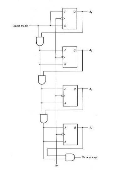
Logic gates are used to decide when to toggle which outputs. Below is an
example of a synchronous binary counter, implemented using J-K flip-flops and
AND gates.
Why "synchronous"?
The difference
between asynchronous and synchronous counters.
In an
asynchronous counter, an external event is used to directly SET or CLEAR a
flip-flop when it occurs. In a synchronous counter however, the external event
is used to produce a pulse that is synchronised with the internal clock. An
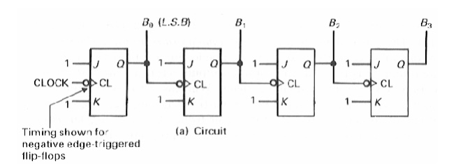
example of an asynchronous counter is a ripple counter. Each flip-flop in the
ripple counter is clocked by the output from the previous flip-flop. Only the
first flip-flop is clocked by an external clock. Below is an example of a 4-bit
ripple counter:
So what's
wrong with asynchronous counters?
Dangers
of asynchronous counters.
Although
the asynchronous counter is easier to implement, it is more
"dangerous" than the synchronous counter. In a complex system, there
are many state changes on each clock edge, and some IC's (integrated circuits)
respond faster than others. If an external event is allowed to affect a system
whenever it occurs, a small percentage of the time it will occur near a clock
transition, after some IC's have responded, but before others have. This
intermingling of transitions often causes erroneous operations. What is worse,
these problems are difficult to test for and difficult to forsee because of the
random time difference between the events.
Different types of synchronous counters
Binary
counters.
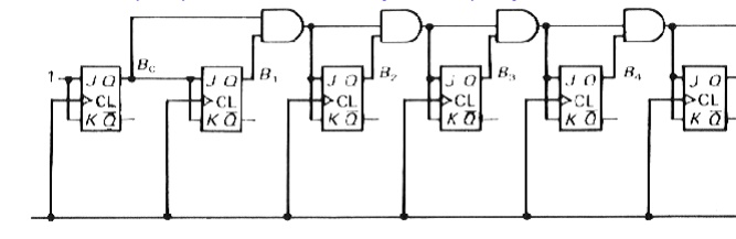
Binary
counters are the simplest form of counters. An N-bit binary counter counts from
0 to (2N - 1) and back to 0 again.
Up/down
counters.
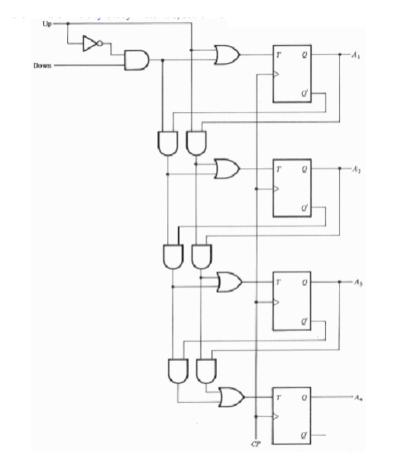
Instead
of just counting up (up counter), counters can be made to count down (down
counter) or both up and down (up-down counter). The diagram below shows an
up-down counter. The counter counts up or down depending on which of the
"up"and "down" inputs are high.
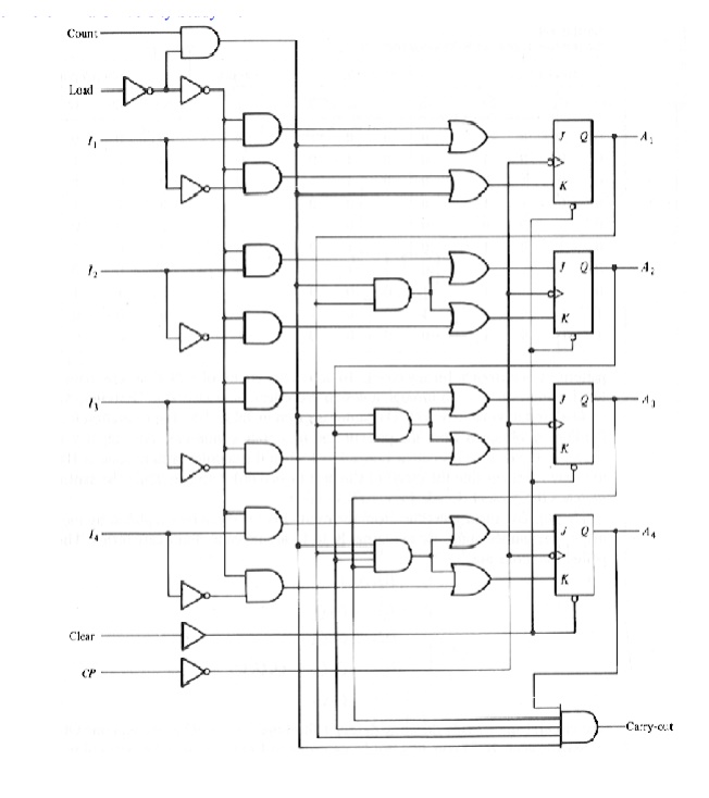
Loadable
counters.
And
instead of counting from 0, a counter can be made to count from a given initial
value. This type of counter is called a loadable counter.
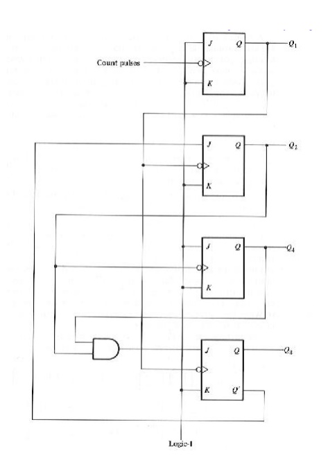
BCD
counters.
A BCD
counter counts in binary-coded decimal from 0000 to 1001 and back to 0000.
Because of the return to 0 after a count of 9, a BCD counter does not have a
regular pattern as in a straight binary count.
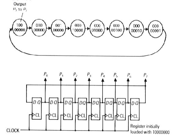
Ring
counters.
A ring
counter is a circular shift register with only one flip-flop being set at any
particular time; all others are cleared. The single bit is shifted from one
flip-flop to the other to produce the sequence of timing signals.
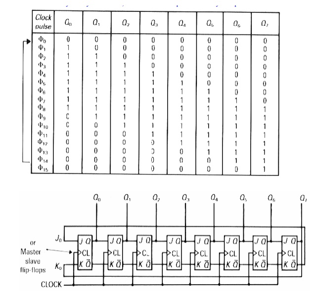
Johnson
counters.
The
Johnson counter, also called the twisted ring counter, is a variation of the
ring counter, with the inverse output of the most significant flip-flop passed
to the input of the least significant flip-flop. The sequence followed begins
with all 0's in the register. The final 0 will cause 1's to be shifted into the
register from the left-hand side when clock pulses are applied. When the first
1 reaches the most significant flip-flop, 0's will be inserted into the first
flip-flop because of the cross-coupling between the output and the input of the
counter.
Related Topics