Chapter: Aquaculture Engineering : Tanks, Basins and Other Closed Production Units
Water inlet design - Aquaculture Engineering
Water inlet design
Correct design of the inlet flow
arrangement to the tank is necessary to ensure even distribution and mixing of
the new incoming water and if self-cleaning is to be attained. This requires
the inlet water pipe to enter below the water surface in the tank and the water
must pass through a narrow nozzle. The force of the inlet water can then be utilized
to create a flow pattern inside the tank (Fig. 13.9). It is also important to
spread the incoming
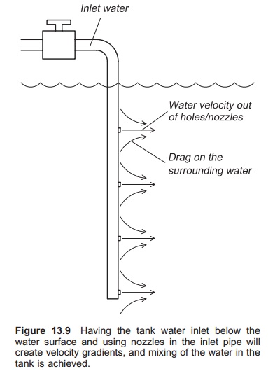
This can be achieved by the use of several holes, splits or nozzles in
the inlet pipe below the water surface. The force of the incoming water will
now be distributed throughout the water column, not just in one place. Improved
distribution of the new oxygen-rich incoming water is also achieved.
The impulse, as the force caused
by the inlet water is called, depends on the water flow and water velocity; it
can be expressed as follows for tanks with a circular flow pattern:
F =rQ (v2− v1)
where:
F =impulse
ρ = water density
Q =water flow
v1=velocity of the water in the tank
v2=velocity out of the holes in the
inlet pipe.
This equation shows that by
increasing Q, the impulse will
increase. The same result is achieved by increasing the velocity of the water
emerging from the holes in the inlet pipe. Decreasing the cross-sectional area
of the holes will increase the velocity of the water. However, the increased
velocity will increase the turbulence and hence the head loss. Recommended
values are below 1.5 m/s in the inlet pipe, while the velocity in the hole (or
split or nozzle) should be below 1.2 m/s.7
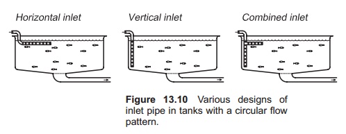
The inlet pipe can be arranged in
several ways depending on the tank design (Fig. 13.10). In tanks with a
circular flow, a horizontal spray inlet has the advantage of creating good
water distribution (primary flow), but the secondary flow is not optimal. The
vertical spray inlet creates both good primary and secondary flow, and is
therefore preferred. It is also possible to use a combined vertical and
horizontal inlet with good results.
Normally a vertical spray inlet
will be placed about one fish width away from the tank wall, so that the fish
can pass behind, and to avoid too much friction from the tank walls. If it is
too close to the wall, friction against the wall will reduce the impulse.
However, in a low tank designed with a diameter : depth ratio of less than 0.2,
the inlet has to be placed further into the tank closer to the drain, to create
a good flow pattern. In silos is it especially difficult to get good inlets and
effective transfer of the impulse, and hence effective water exchange
throughout the water volume. However it may be possible to use several water
inlets in the tanks to improve the flow pattern; testing of the velocity
profile is recommended in such cases. Depending on the current velocity from
the holes in the inlet pipe, the current velocity in tanks with circular flow
is normally in the range 0.15–0.25 m/s.7
In raceways it has proved to be
difficult to create an inlet that distributes the water in a uniform way
throughout the entire cross-sectional area and total length. It is important
that the impulse is distributed over as large a part of the cross-sectional
area as possible. Because of the continuous reduction in water flow velocity close
to the bottom due to friction, there have been experiments in which water was
added at several places over the length of the raceway to improve the velocity
over the total area; this, however, increases the costs.
The velocity of the inlet water
out of the holes or nozzles in the inlet pipe (V2) depends on the design of the nozzle (hole), the area
and the amount of water that has to pass. It can be expressed as follows:
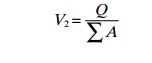
where:
V2=velocity out of the nozzles
Q =water flow out of the nozzles
ΣA = total cross-sectional area of all the nozzles.
The relation between the water
velocity in the inlet pipe and the velocity out of the nozzles will be as
follows:
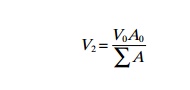
where:
V0=velocity in the inlet pipe
A0=area of the inlet pipe.
Example
An inlet pipe to a circular tank is designed for a water flow
(Q) of 50 l/min. Suggest an
appropriate pipe diameter and area of the nozzles (holes).
First, calculate the area of the inlet pipe:
A = Q/V
Transform the units so that they correspond and take a maximum
water velocity of 1.5 m/s.
50 l/min = 0.00083 m3/s
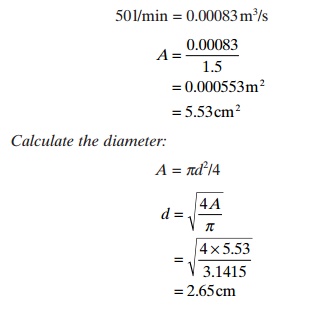
In practice the nearest standard dimension will be used.
Calculate the total nozzle/area
(cross-sectional area) using a velocity of 1.2 m/s.
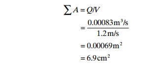
This must then be divided by the number of holes used in the
total water column.
To force the water through the
inlet pipe results in a head loss. Because of this, a minimum head (available
water pressure) is necessary to get the water to flow through the
nozzles/holes. Different shapes of the nozzles/holes will result in different
head loss because of different degrees of turbu-lence created in the nozzles.
This must be taken into consideration when constructing the inlet pipe.
Example
Head loss in the inlet pipe
The inlet pipe has a diameter of 63 mm and a water flow of 300 l/min is used. This gives a water velocity of about 1.6 m/s. Find the head loss when increasing the
water velocity from 1 to 2.5 m/s (f = 0.024).
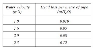
With a water velocity of 2.5 m/s in the inlet
pipe, it is necessary to have a pressure in the pipe of 0.1 mH2O per
metre of pipeline to achieve the necessary water flow.
Related Topics