Chapter: Object Oriented Analysis and Design
UML Component Diagram
UML Component Diagram:
1. Overview:
Component
diagrams are different in terms of nature and behaviour. Component diagrams are
used to model physical aspects of a system. Now the question is what are these
physical aspects? Physical aspects are the elements like executables,
libraries, files, documents etc which resides in a node.
So
component diagrams are used to visualize the organization and relationships
among components in a system. These diagrams are also used to make executable
systems.
2. Purpose:
Component
diagram is a special kind of diagram in UML. The purpose is also different from
all other diagrams discussed so far. It does not describe the functionality of
the system but it describes the components used to make those functionalities.
So from that point component diagrams are used to visualize the physical
components in a system. These components are libraries, packages, files etc.
Component
diagrams can also be described as a static implementation view of a system.
Static implementation represents the organization of the components at a
particular moment. A single component diagram cannot represent the entire
system but a collection of diagrams are used to represent the whole. So the
purpose of the component diagram can be summarized as:
1. Visualize
the components of a system.
2. Construct
executables by using forward and reverse engineering.
3. Describe
the organization and relationships of the components.
3. How to draw Component Diagram?
Component
diagrams are used to describe the physical artifacts of a system. This artifact
includes files, executables, libraries etc. So the purpose of this diagram is
different, Component diagrams are used during the implementation phase of an
application. But it is prepared well in advance to visualize the implementation
details.
Initially
the system is designed using different UML diagrams and then when the artifacts
are ready component diagrams are used to get an idea of the implementation.
This diagram is very important because without it the application cannot be
implemented efficiently.
A
well prepared component diagram is also important for other aspects like
application performance, maintenance etc. So before drawing a component diagram
the following artifacts are to be identified clearly:
1. Files
used in the system.
2. Libraries
and other artifacts relevant to the application.
3. Relationships
among the artifacts.
Now after identifying the artifacts the
following points needs to be followed:
1. Use
a meaningful name to identify the component for which the diagram is to be
drawn.
2. Prepare
a mental layout before producing using tools.
3. Use
notes for clarifying important points.
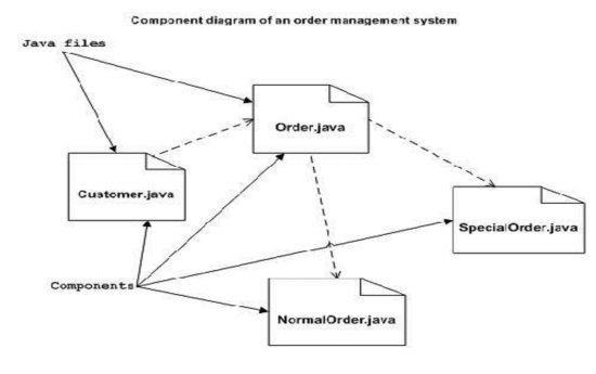
The
following is a component diagram for order management system. Here the
artifacts are files. So the diagram shows the files in the application and
their relationships.
In
actual the component diagram also contains dlls, libraries, folders etc. In the
following diagram four files are identified and their relationships are
produced. Component diagram cannot be matched directly with other UML diagrams
discussed so far. Because it is drawn for completely different purpose.
So
the following component diagram has been drawn considering all the points
mentioned above:
4. Where to use Component Diagrams?
We
have already described that component diagrams are used to visualize the static
implementation view of a system. Component diagrams are special type of UML
diagrams used for different purposes.
These
diagrams show the physical components of a system. To clarify it, we can say
that component diagrams describe the organization of the components in a
system.
Organization
can be further described as the location of the components in a system. These
components are organized in a special way to meet the system requirements. As
we have already discussed those components are libraries, files, executables
etc. Now before implementing the application these components are to be
organized.
This
component organization is also designed separately as a part of project
execution. Component diagrams are very important from implementation perspective.
So the implementation team of an application should have a proper knowledge of
the component details. Now the usage of component diagrams can be described as:
1. Model
the components of a system.
2. Model
database schema.
3. Model
executables of an application.
4. Model
system's source code.
5. Basic Component Diagram Symbols and Notations
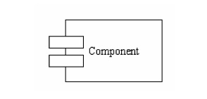
Component
A component is a physical building block
of the system. It is represented as a rectangle with tabs. Learn how to resize
grouped objects like components.
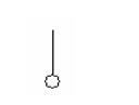
Interface
An interface describes a group of
operations used or created by components.
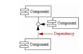
Dependencies
Draw
dependencies among components using dashed arrows. Learn about line styles in
SmartDraw.
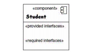
6. Elements of a component diagram:
Rectangle: A single component is
described using a rectangle and having the component‟s name inside it.
<<Component>>Component Name
Additional compartments: Additional
compartments are stacked below the component name. Interfaces provided/required:
Another compartment exists for displaying the interface provided and required
by the component.
Subsystem: A subsystem is represented using a rectangle with stereotype <>subsystem name.
Related Topics