Chapter: Object Oriented Analysis and Design
Concepts: Conceptual Data Modeling
Concepts: Conceptual Data Modeling
1. Introduction
Conceptual
data modeling represents the initial stage in the development of the design of
the persistent data and persistent data storage for the system. In many cases,
the persistent data for the system are managed by a relational database
management system (RDBMS). The business and system entities identified at a
conceptual level from the business models and system requirements will be
evolved through the use-case analysis, use-case design, and database design
activities into detailed physical table designs that will be implemented in the
RDBMS. Note that the Conceptual Data Model discussed in this concept document
is not a separate artifact. Instead it consists of a composite view of
information contained in existing Business Modeling, Requirements, and Analysis
and Design Disciplines artifacts that is relevant to the development of the
Data Model.
The
Data Model typically evolves through the following three general stages:
Conceptual
This
stage involves the identification of the high level key business and system
entities and their relationships that define the scope of the problem to be
addressed by the system. These key business and system entities are defined
using the modeling elements of the UML profile for business modeling included
in the Business Analysis Model and the Analysis Class model elements of the
Analysis Model
Logical
This
stage involves the refinement of the conceptual high level business and system
entities into more detailed logical entities. These logical entities and their
relationships can be optionally defined in a Logical Data Model using the
modeling elements of the UML profile for database design as described in
Guidelines: Data Model. This optional Logical Data Model is part of the
Artifact: Data Model and not a separate RUP artifact.
Physical
This
stage involves the transformation of the logical class designs into detailed
and optimized physical database table designs. The physical stage also includes
the mapping of the database table designs to tablespaces and to the database
component in the database storage design.
The
activities related to database design span the entire software development
lifecycle, and the initial database design activities might start during the
inception phase. For projects that use business modeling to describe the
business context of the application, database design may start at a conceptual
level with the identification of Business Actors and Business Use Cases in the
Business Use-Case Model, and the Business Workers and Business Entities in the
Business Analysis Model. For projects that do not use business modeling, the
database design might start at the conceptual level with the identification of
System Actors and System Use Cases in the Use-Case Model, and the
identification of Analysis Classes in the Analysis Model from the Use-Case
Realizations.
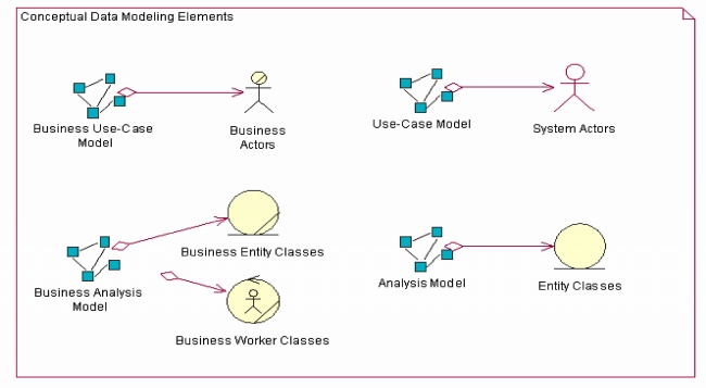
The
figure below shows the set of Conceptual Data Model elements that reside in the
Business Models, Requirements Models, and the Analysis Model.
The
following sections describe the elements of the Business Models, Use-Case
Model, and Analysis Model that can be used to define the initial Conceptual
Data Model for persistent data in the system.
2. Conceptual Data Modeling Elements
Business
Models
Business
Use-Case Model
The
Business Use-Case Model consists of Business Actors and Business Use Cases. The
Business Use Cases represent key business processes that are used to define the
context for the system to be developed. Business Actors represent key external
entities that interact with the business through the Business Use Cases. The
figure below shows a very simple example Business Use-Case Model for an online
auction application.
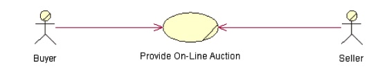
As
entities of significance to the problem of space for the system, Business
Actors are candidate entities for the Conceptual Data Model. In the example
above, the Buyer and Seller Business Actors are candidate entities for which
the online auction application must store information.
Business
Analysis Model
The
Business Analysis Model contains classes that model the Business Workers and
Business Entities identified from analysis of the workflow in the Business Use
Case. Business Workers represent the participating workers that perform the
actions needed to carry out that workflow. Business Entities are
"things" that the Business Workers use or produce during that
workflow. In many cases, the Business Entities represent types of information
that the system must store persistently.
The
figure below shows an example sequence diagram that depicts Business Workers
and Business Entities from one scenario of the Business Use Case titled
"Provide Online Auction" for managing an auction.
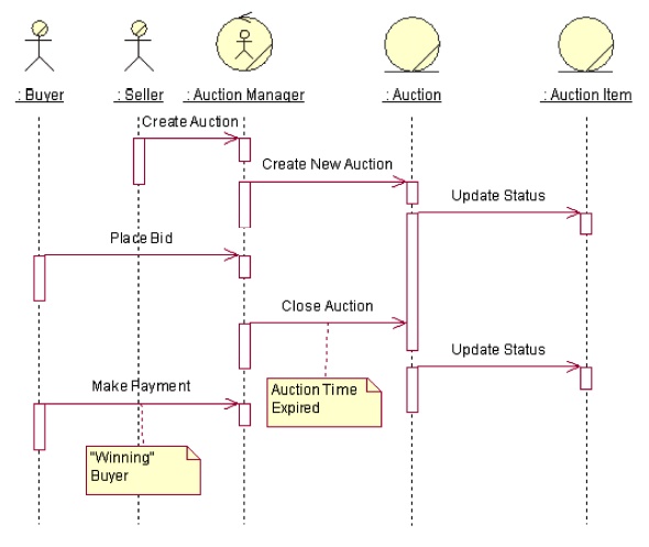
In
this simplified example, the Auction Manager object represents a Business
Worker role that will likely be performed by the online auction management
system itself. The Auction and Auction Item objects are Business Entities that
are used or produced by the Auction Manager worker acting as an agent for the
Seller and Buyer Business Actors. From a database design perspective, the
Auction and Auction Item Business Entities are candidate entities for the
Conceptual Data Model.
Requirements
and Analysis Models
For
projects that do not perform business modeling, the Requirements (System Use
Case) and Analysis Models contain model elements that can be used to develop an
initial Conceptual Data Model. For projects that use business modeling, the
business entities and relationships identified in the Business Analysis Models
are refined and detailed in the Analysis Model as Entity Classes.
System
Use-Case Model
The
System Use-Case Model contains System Actors and System Use Cases that define
the primary interactions of the users with the system. The System Use Cases
define the functional requirements for the system.
From
a conceptual data modeling perspective, the System Actors represent entities
external to the system for which the system might need to store persistent
information. This is important in cases where the System Actor is an external
system that provides data to and/or receives data from the system under
development. System Actors can be derived from the Business Actors in the
Business Use-Case Model and the Business Workers in the Business Analysis
Model.
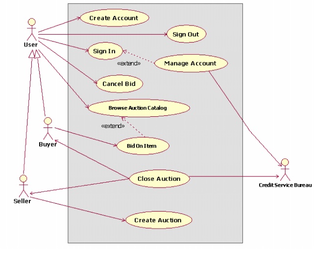
The
figure below depicts the Business Use-Case Model for the online auction system.
In this model, the Buyer and Seller Business Actors are now derived from a
generic User Business Actor. A new System Actor named Credit Service Bureau has
been added to reflect the need to process payments through an external entity.
This new System Actor is another candidate entity for the Conceptual Data
Model.
Analysis
Model
The
Analysis Model contains the Analysis Classes identified in the Use-Case
Realizations for the System Use Cases. The types of Analysis Classes that are
of primary interest from a conceptual data modeling perspective are the Entity
Analysis Classes. As defined in Guidelines: Analysis Class, Entity Analysis
Classes represent information managed by the system that must be stored in a
persistent manner. The Entity Analysis
Classes and their relationships form the
basis of the initial Data Model for the application.
The
conceptual Entity Analysis Classes in the Analysis Model might be refined and
detailed into logical Persistent Design Classes in the Design Model. These
design classes represent candidate tables in the Data Model. The attributes of
the classes are candidate columns for the tables and also represent candidate
keys for them. See Guidelines: Forward-Engineering Relational Databases for a
description of how elements in the Design Model can be mapped to Data Model
elements.
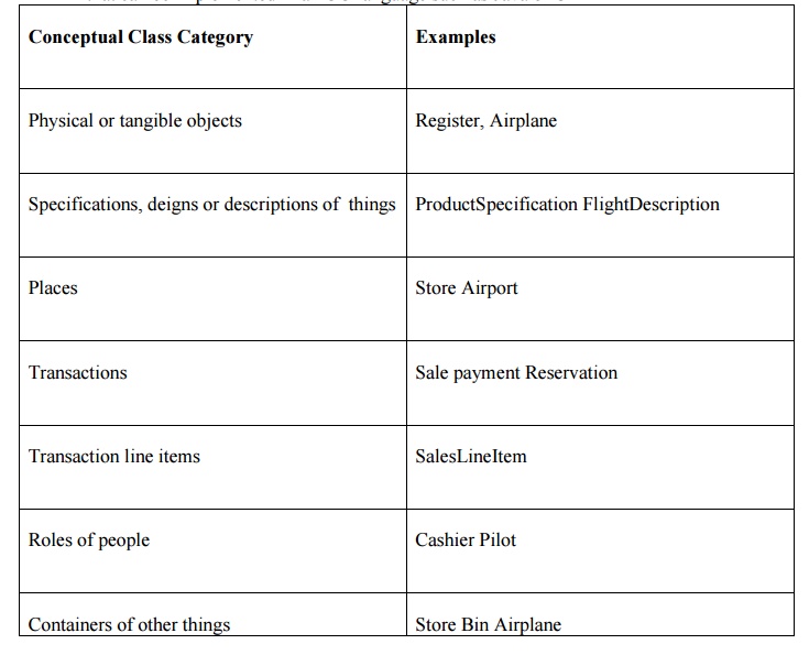
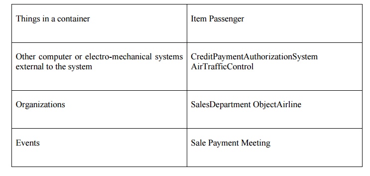
3. Conceptual Class Category List
A
conceptual class is a real-world concept or thing; a conceptual or essential
perspective. At the noun filtering stage we are looking for conceptual classes.
As we move through the design process we will start to design software classes
that represent an implementation perspective of a software component but we
will not get into language specific classes in 466. A conceptual class is not
an implementation class, such as a class that can be implemented in an OO
language such as Java or C++
4. Types of Classes
During
use case realization, we identify mainly four "types" of classes,
boundary classes, data store classes and control classes.
The
entity classes represent the information that the system uses. Examples of
entity classes are: Customer, Product, and Supplier. Entity classes are
essential to the system as the expected functionality of the system includes
maintaining information about them or retrieving information from them.
The
boundary classes represent the interaction between the system and its actors. A
GUI form is an example of a boundary class.
Data
store classes encapsulate the design decisions about data storage and retrieval
strategies. This provides us flexibility to move a n application from database
platform to another.
The
control classes represent the control logic of the system. They implement the
flow of events as given in a use case.
Entity
Classes
Entity
classes are the abstractions of the keys concepts of the system being modelled.
If the steps of the Architectural Analysis have been carried out, many of the
entity classes may have already been identified during those steps.
The
Core functionality and logic of the system are encapsulated in the various
entity classes. For example, if interest is to be calculated and paid to
savings account holders, a savings Account entity class may be responsible for
computing and returning the interest.
You
can normally look for the following types of things as potential entity
classes:
1. Roles
played by people or organizations about which information is required to be
maintained by the system. For Example, Student in a Library Management System,
Vendor in a Purchase Ordering System.
2. Other
physical, tangible things. For example, Book in a Library Management System.
3. Events
that requires remembrance. For example, Reservation and Issue in a Library
Management System.
The
logical data structures (attributes and relationships) of the entity classes
would be designed to hold and manipulate the data according to the system's
requirements. Values of the attributes and their relationships of the entity
class objects are often given by actors. The entity classes are responsible for
storing and managing information in the system.
Entity
class objects are usually persistent, having attributes and relationships that
need to be retained for a long time, sometimes even before the life of system.
An entity class is usually not specific to one use cause realization. Objects
of most entity classes would required in multiple use cases. Sometimes, an
entity object may not be specific to the system itself.
Boundary
Classes
Boundary
classes represent the interaction between the system and its actors. They
insulate the system from changes in the surroundings of the system, such as
user interfaces, and interfaces to other systems.
There
may be various types of boundary classes in a system:
1. User
Interfaces classes: Classes for encapsulating the human user interface of the
system, such as GUI forms.
2. System
Interface Classes: Classes that encapsulate the interaction of the system with
other systems.
3. Device
Interface Classes: Classes that provide the interface to devices that detect
external events.
An
important objective of identifying boundary classes is to ensure that the
entity classes and the control classes are not affected by any changes to the
boundary classes.
Actors
interact with the system only through the boundary classes
User
Interface Classes
A
user interface class represents the interaction between a use case and its
initiating actor. This class has the responsibility of coordinating the
interaction with the actor. A boundary class may have various subsidiary
classes to which some of its responsibilities are delegated. For example, in a
GUI application, there may be multiple forms within a use case.
During
use case analysis, you should use the boundary classes as just place-holders
for the GUI forms. Detailed GUI design is an activity of Class Design. During
Analysis, the emphasis should be only on isolating all environment-dependent
behaviour as boundary classes. These classes will get refined or replaced in
the later stages.
System
Interface Classes
A
system interface class is responsible for interfacing with an external system.
The interface offered by the external system would have been identified by the
developers of that system. Thus, the behaviour of a system interface class
should be derived directly from the interface specifications of the external
system.
System
interface classes achieve the purpose of isolating the internal details of the
external systems, which may change over a period of time. Our system should not
get affected by such changes in the internal details of the external systems.
Device
Interface Classes
Device
interface classes are responsible for interacting with the external devices
that the system may depend upon for receiving inputs or handling outputs.
Examples of such external devices would be: bar code reader, system clock, printer,
etc.
A
device may already have a well-defined interface, which could be used by you
later during design. Therefore, a note of such interface should be made in the
model documentation.
Data
Store Classes
Data
Store classes encapsulate our design decisions about the database structures
which are used to store entity class objects, and to retrieve them later. For
each entity class that required persistence, we create a corresponding data
store class. A data store class typically receives an object of an entity
class, and make it persistence (for example, by inserting a row in a table). At
a later point of time, we may ask the data store class to return the entity
class object.
Encapsulating
the database design designs in data store classes, makes the entity classes
independent of the database structure, and thus provides us greater flexibility
to move an application from one database platform to another.
Controller
Classes
Controller
classes provide co-ordinating behaviour in the system. A typical example would
be a controller class implementing the logic and flow of events of a use case.
Controller
Classes isolates the entity classes and boundary classes from each other,
making the system independent of the changes to the system boundary. They also
isolate the use case specific behaviour from the entity class objects, thus
making them re-usable across use cases and even across systems.
Simple
use cases may be performed without using controller classes, with direct flow
of data between boundary objects and entity objects. However, more complex use
cases usually require and benefit from such controller classes. The
characteristics of controller classes are:
1. They
define the order of events and transactions within a use case. In other words,
they encapsulate the use case-specific behaviour of the system.
2. They
are relatively independent of the changes to the internal structure or
behaviour of the entity classes.
3. They
are nearly independent of changes to the boundary classes.
4. They
may use or set several entity classes, thus coordinating the behaviour of these
entity classes. However, this coordination can be invisible to the
participating entity classes.
Though
most of the times a control class correspond to a single use case, some times a
single controller class may be use to control several use cases. Some tines
there may even be multiple controller classes with in a single use case. As
mentioned earlier, there may be use cases that do not require controller
classes.
Related Topics