Chapter: Object Oriented Analysis and Design
The Use Case Model
The Use Case Model
The
Use Case Model describes the proposed functionality of the new system. A Use
Case represents a discrete unit of interaction between a user (human or
machine) and the system. A Use Case is a single unit of meaningful work; for
example login to system, register with system and create order are all Use
Cases. Each Use Case has a description which describes the functionality that
will be built in the proposed system. A Use Case may 'include' another Use
Case's functionality or 'extend' another Use Case with its own behaviour.
Use
Cases are typically related to 'actors'. An actor is a human or machine entity
that interacts with the system to perform meaningful work
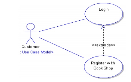
A Use Case description will generally
include:
1. General
comments and notes describing the use case.
2. Requirements
3. Constraints
4. Scenarios
5. Scenario
diagram
Actors
An
Actor is a user of the system. This includes both human users and other
computer systems. An Actor uses a Use Case to perform some piece of work which
is of value to the business. The set of Use Cases an actor has access to
defines their overall role in the system and the scope of their action.
Constraints,
Requirements and Scenarios
The formal specification of a Use Case
includes:
1. Requirements.
These are the formal functional requirements that a Use Case must provide to
the end user. They correspond to the functional specifications found in
structured methodologies. A requirement is a contract that the Use Case will
perform some action or provide some value to the system.
2. Constraints.
These are the formal rules and limitations that a Use Case operates under, and
includes pre- post- and invariant conditions. A pre-condition specifies what
must have already occurred or be in place before the Use Case may start. A
post-condition documents what will be true once the Use Case is complete. An
invariant specifies what will be true throughout the time the Use Case
operates.
3. Scenarios.
Scenarios are formal descriptions of the flow of events that occurs during a
Use Case instance. These are usually described in text and correspond to a
textual representation of the Sequence Diagram.
Includes
and Extends relationships between Use Cases
One
Use Case may include the functionality of another as part of its normal
processing. Generally, it is assumed that the included Use Case will be called
every time the basic path is run. An example may be to list a set of customer
orders to choose from before modifying a selected order - in this case the
<list orders> Use Case may be included every time the <modify
order> Use Case is run.
A
Use Case may be included by one or more Use Cases, so it helps to reduce
duplication of functionality by factoring out common behaviour into Use Cases
that are re-used many times.
One
Use Case may extend the behaviour of another - typically when exceptional
circumstances are encountered. For example, if before modifying a particular
type of customer order, a user must get approval from some higher authority,
then the <get approval> Use Case may optionally extend the regular
<modify order> Use Case.
Sequence
Diagrams
UML
provides a graphical means of depicting object interactions over time in
Sequence Diagrams. These typically show a user or actor, and the objects and
components they interact with in the execution of a use case. One sequence
diagram typically represents a single Use Case 'scenario' or flow of events.
Sequence
diagrams are an excellent way to document usage scenarios and to both capture
required objects early in analysis and to verify object usage later in design.
Sequence diagrams show the flow of messages from one object to another, and as
such correspond to the methods and events supported by a class/object.
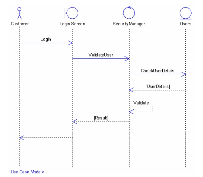
The
diagram illustrated below shows an example of a sequence diagram, with the user
or actor on the left initiating a flow of events and messages that correspond
to the Use Case scenario. The messages that pass between objects will become
class operations in the final model.
Implementation
Diagram
A
Use Case is a formal description of functionality the system will have when
constructed. An implementation diagram is typically associated with a Use Case
to document what design elements (eg. components and classes) will implement
the Use Case functionality in the new system. This provides a high level of
traceability for the system designer, the customer and the team that will
actually build the system. The list of Use Cases that a component or class is
linked to documents the minimum functionality that must be implemented by the
component
Relationships
Between Use Cases
Use cases could be organized using
following relationships:
1. Generalization
2. Association
3. Extend
4. Include
1. Generalization Between Use Cases
Generalization
between use cases is similar to generalization between classes – child use case
inherits properties and behavior of the parent use case and may override the
behavior of the parent.
Notation:
Generalization
is rendered as a solid directed line with a large open arrowhead (same as
generalization between classes).
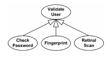
Generalization between use cases
2. Association Between Use Cases
Use
cases can only be involved in binary Associations. Two use cases specifying the
same subject cannot be associated since each of them individually describes a
complete usage of the system.
3. Extend Relationship
Extend is a directed relationship from
an extending use case to an extended
use case that specifies how and when the behavior defined in usually
supplementary (optional) extending use case can be inserted into the behavior
defined in the use case to be extended
Note:
Extended use case is meaningful on its own, independently of the extending use
case, while the extending use case typically defines behavior that is not
necessarily meaningful by itself.
The
extension takes place at one or more extension points defined in the extended
use case.
The
extend relationship is owned by the extending use case. The same extending use
case can extend more than one use case, and extending use case may itself be
extended.
Extend
relationship between use cases is shown by a dashed arrow with an open
arrowhead from the extending use case to the extended (base) use case. The
arrow is labeled with the keyword «extend».

Registration
use case is meaningful on its own, and it could be extended with optional
Get Help On Registration use case
The
condition of the extend relationship as well as the references to the extension
points are optionally shown in a Note attached to the corresponding extend
relationship.
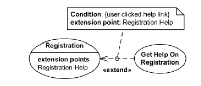
Registration
use case is conditionally extended by Get Help On Registration use case in
extension point Registration Help
Extension
Point
An
extension point is a feature of a use case which identifies (references) a
point in the behavior of the use case where that behavior can be extended by
some other (extending) use case, as specified by an extend relationship.
Extension
points may be shown in a compartment of the use case oval symbol under the
heading extension points. Each extension point must have a name, unique within
a use case. Extension points are shown as text string according to the syntax:
<extension point> ::= <name> [: <explanation>]
The
optional description is given usually as informal text, but can also be given
in other forms, such as the name of a state in a state machine, an activity in
an activity diagram, a precondition, or a postcondition.
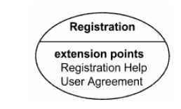
Registration
use case with extension points Registration Help and User Agreement
Extension
points may be shown in a compartment of the use case rectangle with ellipse
icon under the heading extension points.

Extension points of the Registration use
case shown using the rectangle notation
4. Include Relationship
An
include relationship is a directed relationship between two use cases, implying
that the behavior of the required (not optional) included use case is inserted
into the behavior of the including (base) use case. Including use case depends
on the addition of the included use case.
The
include relationship is intended to be used when there are common parts of the
behavior of two or more use cases. This common part is extracted into a
separate use case to be included by all the base use cases having this part in
common.
Execution
of the included use case is analogous to a subroutine call or macro command in
programming. All of the behavior of the included use case is executed at a
single location in the including use case before execution of the including use
case is resumed.
As
the primary use of the include relationship is to reuse common parts, including
use cases are usually not complete by themselves but dependent on the included
use cases.
Include
relationship between use cases is shown by a dashed arrow with an open
arrowhead from the including (base) use case to the included (common part) use
case. The arrow is labeled with the keyword «include».

Four
Phases of Unified Process
The
Unified Process consists of cycles that may repeat over the long-term life of a
system. A cycle consists of four phases: Inception, Elaboration, Construction
and Transition. Each cycle is concluded with a release, there are also releases
within a cycle. Let's briefly review the four phases in a cycle:
Inception
Phase - During the inception phase the core idea is
developed into a product vision. In this phase, we review and confirm our
understanding of the core business drivers. We want to understand the business
case for why the project should be attempted. The inception phase establishes
the product feasibility and delimits the project scope.
Elaboration
Phase - During the elaboration phase the majority of the
Use Cases are specified in detail and the system architecture is designed. This
phase focuses on the "Do-Ability" of the project. We identify
significant risks and prepare a schedule, staff and cost profile for the entire
project.
Construction
Phase - During the construction phase the product is moved
from the architectural baseline to a system complete enough to transition to
the user community. The architectural baseline grows to become the completed
system as the design is refined into code.
Transition Phase - In the transition phase the goal is to ensure that the requirements have been met to the satisfaction of the stakeholders. This phase is often initiated with a beta release of the application. Other activities include site preparation, manual completion, and defect identification and correction. The transition phase ends with a postmortem devoted to learning and recording lessons for future cycles.
Related Topics