Chapter: Object Oriented Analysis and Design
UML Deployment Diagram
UML Deployment Diagram
1. Overview:
Deployment diagrams are used to visualize the topology of the physical components of a system where the software components are deployed. So deployment diagrams are used to describe the static deployment view of a system.
Deployment
diagrams consist of nodes and their relationships.
2. Purpose:
The
name Deployment itself describes the purpose of the diagram. Deployment
diagrams are used for describing the hardware components where software
components are deployed. Component diagrams and deployment diagrams are closely
related. Component diagrams are used to describe the components and deployment
diagrams shows how they are deployed in hardware. UML is mainly designed to
focus on software artifacts of a system. But these two diagrams are special
diagrams used to focus on software components and hardware components. So most
of the UML diagrams are used to handle logical components but deployment
diagrams are made to focus on hardware topology of a system. Deployment
diagrams are used by the system engineers.
The
purpose of deployment diagrams can be described as:
1. Visualize
hardware topology of a system.
2. Describe
the hardware components used to deploy software components.
3. Describe
runtime processing nodes.
3. How to draw Component Diagram?
Deployment
diagram represents the deployment view of a system. It is related to the
component diagram. Because the components are deployed using the deployment
diagrams. A deployment diagram consists of nodes. Nodes are nothing but physical
hardwares used to deploy the application. Deployment diagrams are useful for
system engineers. An efficient deployment diagram is very important because it
controls the following parameters
1. Performance
2. Scalability
3. Maintainability
4. Portability
So
before drawing a deployment diagram the following artifacts should be
identified:
1. Nodes
2. Relationships
among node
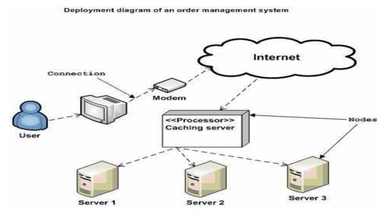
The
following deployment diagram is a sample to give an idea of the deployment view
of order management system. Here we have shown nodes as:
1. Monitor
2. Modem
3. Caching
server
4. Server
The
application is assumed to be a web based application which is deployed in a
clustered environment using server 1, server 2 and server 3. The user is
connecting to the application using internet. The control is flowing from the caching
server to the clustered environment. So the following deployment diagram has been
drawn considering all the points mentioned above:
4. Where to use Deployment Diagrams?
Deployment
diagrams are mainly used by system engineers. These diagrams are used to
describe the physical components (hardwares), their distribution and
association. To clarify it in details we can visualize deployment diagrams as
the hardware components/nodes on which software components reside. Software
applications are developed to model complex business processes.
Only
efficient software applications are not sufficient to meet business
requirements. Business requirements can be described as to support increasing
number of users, quick response time etc. To meet these types of requirements
hardware components should be designed efficiently and in a cost effective way.
Now
a day's software applications are very complex in nature. Software applications
can be stand alone, web based, distributed, mainframe based and many more. So
it is very important to design the hardware components efficiently. So the
usage of deployment diagrams can be described as follows:
1. To
model the hardware topology of a system.
2. To
model embedded system.
3. To
model hardware details for a client/server system.
4. To
model hardware details of a distributed application.
5. Forward
and reverse engineering.
Deployment
Diagrams
Deployment
diagram shows execution architecture of systems that represent the assignment
(deployment) of software artifacts to deployment targets (usually nodes).
Nodes
represent either hardware devices or software execution environments. They
could be connected through communication paths to create network systems of
arbitrary complexity. Artifacts represent concrete elements in the physical
world that are the result of a development process and are deployed on nodes.
Note,
that components were directly deployed to nodes in UML 1.x deployment diagrams.
In UML 2.x artifacts are deployed to nodes, and artifacts could manifest
components. So components are now deployed to nodes indirectly through
artifacts.
The
following nodes and edges are typically drawn in a UML deployment diagram:
artifact, association between artifacts, dependency between artifacts,
component, manifestation, node, device, execution environment, composition of
nodes, communication path, deployment specification, deployment specification
dependency, deployment specification association, deployment.
Artifact
An
artifact is a classifier that represents some physical entity, piece of
information that is used or is produced by a software development process, or
by deployment and operation of a system. Artifact is source of a deployment to
a node. A particular instance (or "copy") of an artifact is deployed
to a node instance.
Artifacts
may have properties that represent
features of the artifact, and
operations that can
be performed on
its instances. Artifacts
have ileName attribute - a concrete name that is used to refer to the artifact in a physical context - e.g. file name or URI. Some real
life examples of artifacts are:
1. model
file
2. source
file
3. script
4. binary
executable file
5. text
document
6. mail
message
7. table
in a database
Standard
stereotypes can be further specialized into implementation and platform
specific stereotypes in profiles. For example, an EJB profile might define
«jar» as a subclass of «executable» for executable Java archives. Specific
profiles are expected to stereotype artifact to model sets of files (e.g., as
characterized by a "file extension" on a file system).
Artifacts
are deployed to a deployment target.
Instance specification was extended
in UML to allow instances of
artifacts to be deployed artifacts in a deployment
relationship. An artifact is presented using an ordinary class rectangle with
the keyword «artifact». Examples in UML specification also show document icon
in upper right corner.

Associations
Between Artifacts
Artifacts
can be involved in associations to other artifacts, e.g. composition
associations. For instance,
a deployment descriptor
artifact for a component may be contained within the
artifact that manifests that component. In that way, the component and its
descriptor are deployed to a node instance as one artifact instance.
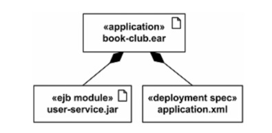
Application
book-club.ear artifact contains EJB user-service.jar artifact and deployment
descriptor.
Dependency
Between Artifacts
Artifacts can be involved in dependency
relationship with other artifacts.
Dependency
between artifacts is notated in the same way as general dependency, i.e. as a
general dashed line with an open arrow head directed from client artifact to
supplier artifact.
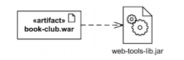
The book-club.war artifact depends on
web-tools-lib.jar artifact.
Artifact
Manifestation
Manifestation is an abstraction
relationship which represents the concrete physical rendering of one or more
model elements by an artifact or utilization of the model elements in the
construction or generation of the artifact. An artifact manifests one or more
model elements.
Note,
that since UML 2.0 artifacts can manifest any packageable element, not just
component as it was in previous versions of UML. The artifact owns the
manifestations, each representing the utilization of a packageable element.
Specific profiles are expected to stereotype the manifestation relationship to
indicate particular forms of manifestation. For example, «tool generated» and
«custom code» might be two manifestations for different classes embodied in an
artifact.
A
manifestation is notated in the same way as abstraction dependency, i.e. as a
dashed line with an open arrow head directed from artifact to packageable
element, (e.g. to component or package) and is labeled with the keyword «manifest».
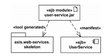
EJB
component UserService and skeleton of web services are manifested by EJB module
user-service.jar artifact
In
UML 1.x, the concept of manifestation was referred to as implementation and
annotated as «implement». Since this was one of the many uses of the word
"implementation" this has been replaced in UML 2.x by «manifest».
Deployment
Target
Artifacts
are deployed to deployment targets. Deployment target is the location for a
deployed artifact.
Deployment
target owns the set of deployment that target it. Deployment target is
specialized by: node
property
Instance
specification was extended in UML 2.0 to allow instance of a node to be deployment
target in a deployment relationship.
Property
was also extended in UML 2.0 with the capability of being a deployment target
in a deployment relationship. This enables modeling the deployment to hierarchical nodes that have properties
functioning as internal parts. Deployment target has no specific notation by
itself, see notations for subclasses.
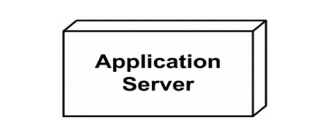
Node
A Node
is a deployment
target which represents computational
resource upon which artifacts may be deployed for execution. A Node is shown as a perspective, 3-dimensional view
of a cube.
Node is associated with a Deployment of
an Artifact. It is also associated with a set of Elements that are deployed on
it. This is a derived association in that these Packageable Elements are
involved in a Manifestation of an Artifact that is deployed on the Node. Nodes
may have an internal structure defined in terms of parts and connectors
associated with them for advanced modeling applications. Parts of node could be
solely of type Node.
Hierarchical
nodes (i.e., nodes within nodes) can be modeled using composition associations,
or by defining an internal structure for advanced modeling applications. Nodes
can be interconnected through communication paths to define network structures.
Communication
paths can be defined between nodes such as “application server” and “client
workstation” to define the possible communication paths between nodes.
Specific network topologies can then be
defined through links between node instances. Node is specialized by:
1. device
2. execution
environment
Device
A
device is a subclass of node which represents a physical computational resource
with processing capability upon which artifacts may be deployed for execution.
A
device is rendered as a node (perspective, 3-dimensional view of a cube)
annotated with keyword «device
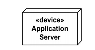
Application
Server device Device may be depicted using custom icon. UML provides no
standard stereotypes for devices. Examples of non-normative stereotypes for
devices are:
1. «application
server»
2. «client
workstation»
3. «mobile
device»
4. «embedded
device
Profiles, stereotypes, and tagged values
could be used to provide custom icons and properties for the devices.

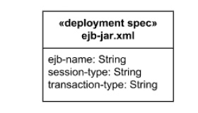
Deployment Specification
A
deployment specification is an artifact that specifies a set of deployment
properties that determine execution parameters of a component artifact that is
deployed on a node. A deployment specification can be aimed at a specific type
of container for a components.
A
deployment specification is a general mechanism to parameterize a deployment
relationship, as is common in various hardware and software technologies.
The
deployment specification element is expected to be extended in specific
component profiles. Non-normative examples of the standard stereotypes that a
profile might add to deployment specification are, for example,
«concurrencyMode» with tagged values {thread, process, none}, or
«transactionMode» with tagged values {transaction, nestedTransaction, none}. A
deployment specification at specification level is graphically displayed as a
classifier rectangle with optional deployment properties in a compartment.
A component deployment is the deployment
of one or more artifacts or artifact instances to a deployment target,
optionally parameterized by a deployment specification. Examples are
executables and configuration files. The deployment relationship between a
deployed artifact and a deployment target can be defined at the “type” level and
at the “instance level.”
For example,
a „type level‟deployment relationship
can be defined
between an “application server”
Node and an “order entry request handler” executable Artifact. At the „instance
level‟3 specific instances “appserver1” ... “app-server3” may be the deployment
target for six “request handler*” instances. For modeling complex deployment
target models consisting of nodes with a composite structure defined through
„parts,‟a Property (that functions as a part) may also be the target of a
deployment. Deployment diagram shows deployed artifacts contained within a
deployment target symbol.
Related Topics