Chapter: Basic Electrical and Electronics Engineering : Digital Electronics
The Digital Encoder
The Digital Encoder
Unlike a multiplexer that selects one individual data input line
and then sends that data to a single output line or switch, a Digital Encoder more commonly called a Binary Encoder takes ALL its data inputs one
at a time and then converts them into a
single encoded output. So we can say that a binary encoder, is a multi-input
combinational logic circuit that converts the logic level "1" data at
its inputs into an equivalent binary code at its output. Generally, digital
encoders produce outputs of 2-bit, 3-bit or 4-bit codes depending upon the
number of data input lines. An "n-bit" binary encoder has 2n input lines and n-bit output lines with common
types that include 4-to-2, 8-to-3 and 16-to-4 line configurations. The output
lines of a digital encoder generate the binary equivalent of the input line
whose value is equal to "1" and are available to encode either a
decimal or hexadecimal input pattern to typically a binary or B.C.D. output
code.
4-to-2 Bit Binary
Encoder
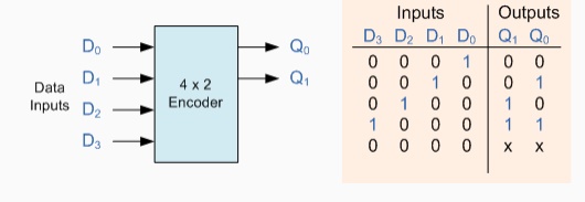
One of the main disadvantages of standard digital encoders is
that they can generate the
wrong output code when there is more than one input present at logic level
"1". For example, if we make inputs D1 and D2 HIGH at logic
"1" at the same time, the resulting output is
neither at "01" or at "10" but will be at "11"
which is an output binary number that is different to the actual input present.
Also, an output code of all
logic "0"s can be generated when all of its inputs are at
"0" OR when input D0 is equal to one.
One simple way to overcome this problem is to
"Prioritise" the level of each input pin and if there was more than
one input at logic level "1" the actual output code would only
correspond to the input with the highest designated priority. Then this type of
digital encoder is known commonly as a Priority
Encoder or P-encoder for short.
Priority Encoders
Priority
Encoders solve the problem
mentioned above by allocating a priority level to each input. The encoder output corresponds to the currently
active input with the highest priority. So when an input with a higher priority
is present, all other inputs with a lower priority will be ignored. Priority
encoders come in many forms with an example of an 8-input priority encoder
along with its truth table shown below.
8-to-3 Bit Priority
Encoder
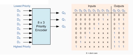
Priority encoders are available in standard IC form and the TTL
74LS148 is an 8 to 3 bit
priority encoder which has eight active LOW (logic "0") inputs and
provides a 3-bit code of the highest ranked input at its output. Priority
encoders output the highest order input first for example, if input lines
"D2", "D3" and "D5" are applied
simultaneously the output code would be for input "D5" ("101") as
this has the highest order out of the 3 inputs. Once input "D5" had been removed the
next highest output code would be for input "D3" ("011"),
and so on.
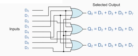
The Boolean expression for this 8-to-3 encoder above with inputs
D0 to D7 and
outputs Q0, Q1, Q2 is given as:
Q0 = D1 + D3 + D5 +
D7
Q1 = D2 + D3 + D6 +
D7
Q2 = D4 + D5 + D6 +
D7
Then the implementation of these Boolean expression outputs
above using individual OR gates is as
follows.
Digital Encoder
using Logic Gates
Binary Decoder
A Decoder is the
exact opposite to that of an "Encoder" we looked at in the last
tutorial. It is basically, a combinational type logic circuit that converts the
binary code data at its input into one of a number of different output lines,
one at a time producing an
equivalent decimal code at its output. Binary
Decoders have inputs of 2-bit, 3-bit or 4-bit codes depending upon the
number of data input lines, and a n-bit
decoder has 2n output lines. Therefore,
if it receives n inputs (usually grouped as
a binary or Boolean number) it activates one and only one of its 2n outputs based on that
input with all other outputs deactivated. A decoders output code normally has
more bits than its input code and practical binary decoder circuits include,
2-to-4, 3-to-8 and 4-to-16 line configurations.
A binary decoder converts coded inputs into coded outputs, where
the input and output codes
are different and decoders are available to "decode" either a Binary
or BCD (8421 code) input pattern to typically a Decimal output code. Commonly
available BCD-to-Decimal decoders include the TTL 7442 or the CMOS 4028. An
example of a 2-to-4 line decoder along with its truth table is given below. It
consists of an array of four NAND
gates, one of which is selected for each combination of the input signals A and B.
A 2-to-4 Binary
Decoders.
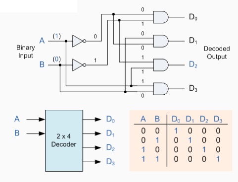
In this simple example of a 2-to-4 line binary decoder, the
binary inputs A and B determine which output line from D0 to D3 is
"HIGH" at logic level "1" while the remaining outputs are
held "LOW" at logic "0" so only one output can be active
(HIGH) at any one time. Therefore, whichever output line is "HIGH"
identifies the binary code present at the input, in other words it
"de-codes" the binary input and these types of binary decoders are
commonly used as Address Decoders in
microprocessor memory applications.
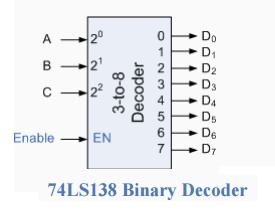
Some binary decoders have an additional input labelled
"Enable" that controls the outputs from the device. This allows the
decoders outputs to be turned "ON" or "OFF" and we can see that the logic diagram of
the basic decoder is identical to that of the basic demultiplexer. Therefore,
we say that a demultiplexer is a decoder with an additional data line that is
used to enable the decoder. An alternative way of looking at the decoder
circuit is to regard inputs A,
B and C as address signals. Each
combination of A, B or C defines a unique address
which can access a location having that address.
Sometimes it is required to have a Binary Decoder with a number of outputs greater than is available,
or if we only have small devices available, we can combine multiple decoders
together to form larger decoder networks as shown. Here a much larger 4-to-16
line binary decoder has been implemented using two smaller 3-to-8 decoders.
A 4-to-16 Binary
Decoder Configuration.
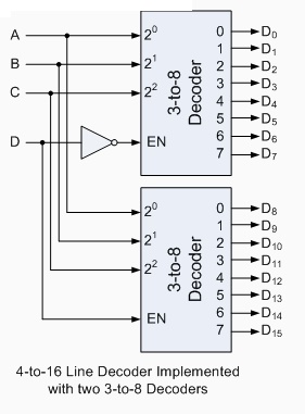
Inputs A, B, C are used to select
which output on either decoder will be at logic "1" (HIGH) and input D is used with the enable
input to select which encoder either the first or second will output the
"1
BCD to 7-Segment
Display Decoder
As we saw in the previous tutorial, a Decoder IC, is a device which converts one digital format into another and the most commonly
used device for doing this is the Binary Coded Decimal (BCD) to
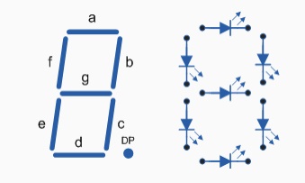
7-Segment Display Decoder. 7-segment LED
(Light Emitting Diode) or LCD
(Liquid Crystal) displays, provide a very convenient way of displaying
information or digital data in the form of numbers, letters or even
alpha-numerical characters and they consist of 7 individual LED's (the
segments), within one single display package.
In order to produce the
required numbers or HEX characters from 0
to 9 and A to F respectively, on the
display the correct combination of LED segments need to be illuminated and BCD to 7-segment Display Decoders such
as the 74LS47 do just that. A standard 7-segment LED display generally has 8
input connections, one for each LED segment and one that acts as a common terminal
or connection for all the internal segments. Some single displays have an
additional input pin for the decimal point in their lower right or left hand
corner.
There are two important types of 7-segment LED digital display.
The Common Cathode Display (CCD) - In the common cathode display, all the
cathode connections of the LED's are joined together to logic "0" and
the individual segments are illuminated by application of a "HIGH",
logic "1" signal to the individual Anode terminals.
The Common Anode Display (CAD) - In the common anode display, all the anode
connections of the LED's are joined together to logic "1" and the
individual segments are illuminated by connecting the individual Cathode
terminals to a "LOW", logic "0" signal.
7-Segment Display
Format
Truth Table for a
7-segment display
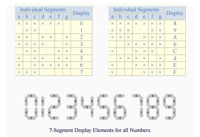
7-Segment Display Elements for all Numbers.
It can be seen that to display any single digit number from 0 to 9 or letter from A to F, we would need 7 separate segment
connections plus one additional connection for the LED's "common" connection. Also as the
segments are basically a standard light emitting diode, the driving circuit
would need to produce up to 20mA of current to illuminate each individual
segment and to display the number 8, all 7 segments would need to be lit resulting a total current
of nearly 140mA, (8 x 20mA). Obviously, the use of so many connections and
power consumption is impractical for some electronic or microprocessor based
circuits and so in order to reduce the number of signal lines required to drive
just one single display, display decoders such as the BCD to 7-Segment Display
Decoder and Driver IC's are used instead.
Binary Coded
Decimal
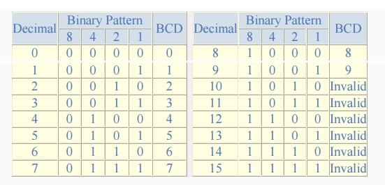
Binary Coded Decimal (BCD or "8421" BCD) numbers are made up using just 4 data bits (a nibble or half a byte)
similar to theHexadecimal numbers we saw in the binary tutorial, but unlike
hexadecimal numbers that range in full from 0 through to F, BCD numbers only range
from 0 to 9, with the binary number patterns
of 1010 through to 1111 (A to F) being invalid inputs for
this type of display and so are not used as shown below.
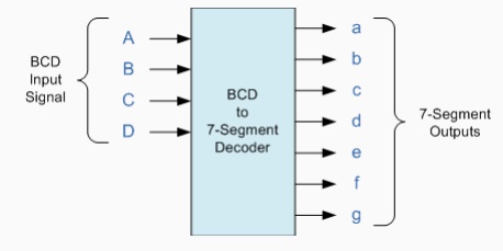
BCD to 7-Segment
Display Decoders
A binary coded decimal (BCD) to 7-segment display decoder such
as the TTL 74LS47 or 74LS48, have 4 BCD inputs and 7 output lines, one for each
LED segment. This allows a smaller 4-bit binary number (half a byte) to be used
to display all the denary numbers from 0 to 9 and by adding two
displays together, a full range of numbers from 00 to 99 can be displayed
with just a single byte of 8 data bits.
BCD to 7-Segment
Decoder
The use of packed BCD allows two BCD digits to be stored within
a single byte (8-bits) of data, allowing a single data byte to hold a BCD
number in the range of 00 to 99.
Related Topics