Waveform Generators - Sine Wave Generators (Oscillators) | Linear Integrated Circuits : Waveform Generators and Special Function ICs
Chapter: Linear Integrated Circuits : Waveform Generators and Special Function ICs
Sine Wave Generators (Oscillators)
Sine Wave
Generators (Oscillators)
Sine
wave oscillator circuits use phase shifting techniques that usually employ
┬Ę
Two
RC tuning networks, and
┬Ę
Complex
amplitude limiting circuitry
RC Phase Shift Oscillator
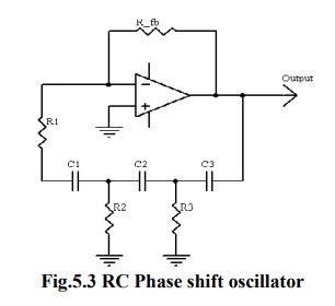
RC
phase shift oscillator using op-amp in inverting amplifier introduces the phase
shift of 180┬║ between input and output. The feedback network consists of 3 RC
sections each producing 60┬║ phase shift. Such a RC phase shift oscillator using
op-amp is shown in the figure.
The
output of amplifier is given to feedback network. The output of feedback
network drives the amplifier. The total phase shift around a loop is 1800 of
amplifier and 180 ![]() due to
3 RC sections, thus 360 ┬║. This satisfies the required condition for positive
feedback and circuit works as an oscillator.
due to
3 RC sections, thus 360 ┬║. This satisfies the required condition for positive
feedback and circuit works as an oscillator.
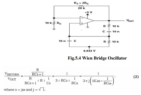
The loop phase shift is ŌĆō180┬░ when the phase shift of each section is ŌĆō60┬░, and this occurs when Žē = 2ŽĆf = 1.732/RC because the tangent 60┬░ = 1.73. The magnitude of ╬▓ at this point is (1/2)3, so the gain, A, must be equal to 8 for the system gain to be equal to 1.
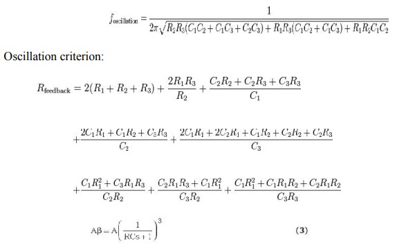
Wien Bridge Oscillator:
Figure
5. 3 give the Wien-bridge circuit configuration. The loop is broken at the
positive input, and the return signal is calculated in Equation 2 below.
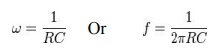
When
Žē = 2ŽĆf = 1/RC, the feedback is in phase (this is positive feedback), and the
gain is 1/3, so oscillation requires an amplifier with a gain of 3. When RF =
2RG, the amplifier gain is 3 and oscillation occurs at f = 1/2ŽĆRC. The circuit
oscillated at 1.65 kHz rather than 1.59 kHz with the component values shown in
Figure 3, but the distortion is noticeable.
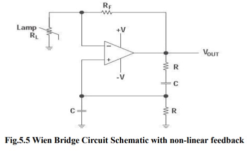
Figure
4 shows a Wien-bridge circuit with non-linear feedback. The lamp resistance,
RL, is nominally selected as half the feedback resistance, RF, at the lamp
current established by RF and RL. The non-linear relationship between the lamp
current and resistance keeps output voltage changes small.
If
a voltage source is applied directly to the input of an ideal amplifier with feedback, the input current will be:
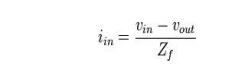
Where
vin is the input voltage, vout is the output voltage, and Zf is the feedback impedance. If the
voltage gain of the amplifier is defined as:
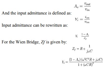
If
Av is greater than 1, the input
admittance is a negative resistance in parallel with an inductance.
The
inductance is:
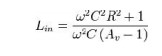
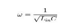
If
a capacitor with the same value of C
is placed in parallel with the input, the circuit has a natural resonance at:
Substituting
and solving for inductance yields:
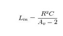
If
Av is chosen to be 3: Lin = R2C
Substituting
this value yields:
Similarly,
the input resistance at the frequency above is:
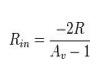
For
Av = 3: Rin
= ŌłÆ R
If
a resistor is placed in parallel with the amplifier input, it will cancel some
of the negative resistance. If the net resistance is negative, amplitude will
grow until clipping occurs.
Similarly,
if the net resistance is positive, oscillation amplitude will decay. If a
resistance is added in parallel with exactly the value of R, the net resistance
will be infinite and the circuit can sustain stable oscillation at any
amplitude allowed by the amplifier.
Increasing
the gain makes the net resistance more negative, which increases amplitude. If gain
is reduced to exactly 3 when suitable amplitude is reached, stable, low
distortion oscillations will result.
Amplitude
stabilization circuits typically increase gain until suitable output amplitude is
reached. As long as R, C, and the amplifier are linear, distortion will be
minimal.
Related Topics