Chapter: physics 11th 12th standard school college definition answer assignment examination viva question
Electrostatic induction
Electrostatic induction
It is possible to obtain charges without any contact with another charge. They are known as induced charges and the phenomenon of producing induced charges is known as electrostatic induction. It is used in electrostatic machines like Van de Graaff generator and capacitors.
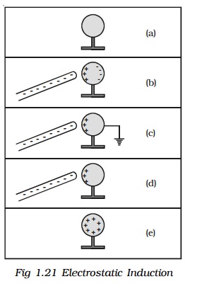
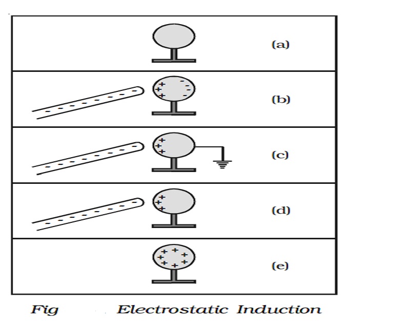
Fig 1.21 shows the steps involved in charging a metal sphere by induction.
a. There is an uncharged metallic sphere on an insulating stand.
b. When a negatively charged plastic rod is brought close to the sphere, the free electrons move away due to repulsion and start pilling up at the farther end. The near end becomes positively charged due to deficit of electrons. This process of charge distribution stops when the net force on the free electron inside the metal is zero (this process happens very fast).
c. When the sphere is grounded, the negative charge flows to the ground. The positive charge at the near end remains held due to attractive forces.
d. When the sphere is removed from the ground, the positive charge continues to be held at the near end.
e. When the plastic rod is removed, the positive charge spreads uniformly over the sphere.
1. Capacitance of a conductor
When a charge q is given to an isolated conductor, its potential will change. The change in potential depends on the size and shape of the conductor. The potential of a conductor changes by V, due to the charge q given to the conductor.
q α V or q = CV
i.e. C = q/V
Here C is called as capacitance of the conductor.
The capacitance of a conductor is defined as the ratio of the charge given to the conductor to the potential developed in the conductor.
The unit of capacitance is farad. A conductor has a capacitance of one farad, if a charge of 1 coulomb given to it, rises its potential by 1 volt.
The practical units of capacitance are µF and pF.
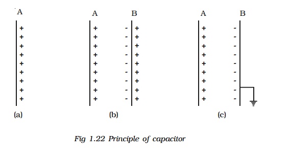
Principle of a capacitor
Consider an insulated conductor (Plate A) with a positive charge 'q' having potential V (Fig 1.22a). The capacitance of A is C = q/V. When another insulated metal plate B is brought near A, negative charges are induced on the side of B near A. An equal amount of positive charge is induced on the other side of B (Fig 1.22b). The negative charge in B decreases the potential of A. The positive charge in B increases the potential of A. But the negative charge on B is nearer to A than the positive charge on B. So the net effect is that, the potential of A decreases. Thus the capacitance of A is increased.
If the plate B is earthed, positive charges get neutralized (Fig 1.22c). Then the potential of A decreases further. Thus the capacitance of A is considerably increased.
The capacitance depends on the geometry of the conductors and nature of the medium. A capacitor is a device for storing electric charges.
2. Capacitance of a parallel plate capacitor
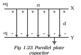
The parallel plate capacitor consists of two parallel metal plates X and Y each of area A, separated by a distance d, having a surface charge density σ . The medium between the plates is air. A charge +q is given to the plate X. It induces a charge -q on the upper surface of earthed plate Y. When the plates are very close to each other, the field is confined to the region between them. The electric lines of force starting from plate X and ending at the plate Y are parallel to each other and perpendicular to the plates.
By the application of Gauss's law, electric field at a point between the two plates is,
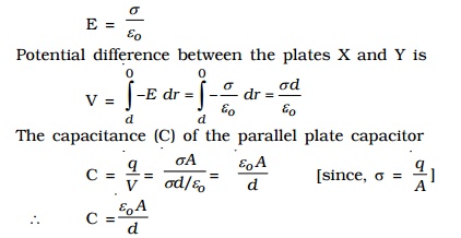
The capacitance is directly proportional to the area (A) of the lates and inversely proportional to their distance of separation (d).
3. Dielectrics and polarisation
Dielectrics
A dielectric is an insulating material in which all the electrons are tightly bound to the nucleus of the atom. There are no free electrons to carry current. Ebonite, mica and oil are few examples of dielectrics. The electrons are not free to move under the influence of an external field.
Polarisation
A nonpolar molecule is one in which the centre of gravity of the positive charges (protons) coincide with the centre of gravity of the negative charges (electrons). Example: O2, N2, H2. The nonpolar molecules do not have a permanent dipole moment.
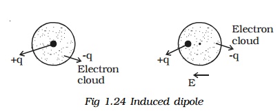
If a non polar dielectric is placed in an electric field, the centre of charges get displaced. The molecules are then said to be polarised and are called induced dipoles. They acquire induced dipole moment p in the direction of electric field (Fig 1.24).
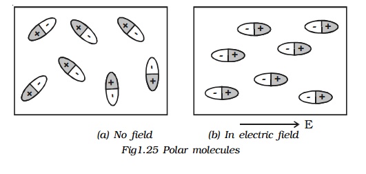
A polar molecule is one in which the centre of gravity of the positive charges is separated from the centre of gravity of the negative charges by a finite distance. Examples : N2O, H2O, HCl, NH3. They have a permanent dipole moment. In the absence of an external field, the dipole moments of polar molecules orient themselves in random directions. Hence no net dipole moment is observed in the dielectric. When an electric field is applied, the dipoles orient themselves in the direction of electric field. Hence a net dipole moment is produced (Fig 1.25).
The alignment of the dipole moments of the permanent or induced dipoles in the direction of applied electric field is called polarisation or electric polarisation.
The magnitude of the induced dipole moment p is directly proportional to the external electric field E.
p α E or p = α E, where α is the constant of proportionality and
4. Polarisation of dielectric material
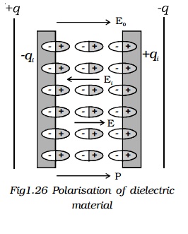
Consider a parallel plate capacitor with +q and -q charges. Let Eo be the electric field between the plates in air. If a dielectric slab is introduced in the space between them, the dielectric slab gets polarised. Suppose +qi and -qi be the induced surface charges on the face of dielectric opposite to the plates of capacitor (Fig 1.26). These induced charges produce their own field Ei which opposes the electric field Eo. So, the resultant field, E < Eo. But the direction of E is in the direction of Eo.
? E = Eo + (-Ei)
(? Ei is opposite to the direction of Eo)
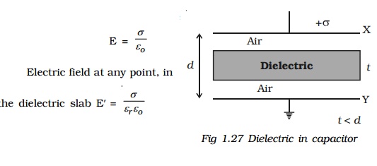
5. Capacitance of a parallel plate capacitor with a dielectric medium.
Consider a parallel plate capacitor having two conducting plates X and Y each of area A, separated by a distance d apart. X is given a positive charge so that the surface charge density on it is ? and Y is earthed.
Let a dielectric slab of thick-ness t and relative permittivity ?r be introduced between the plates (Fig.1.27).
Thickness of dielectric slab = t
Thickness of air gap = (d-t) Electric field at any point in the air between the plates,
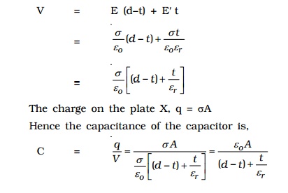
The total potential difference between the plates, is the work done in crossing unit positive charge from one plate to another in the field E over a distance (d-t) and in the field E' over a distance t, then
Effect of dielectric
In capacitors, the region between the two plates is filled with dielectric like mica or oil.
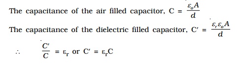
since, εr > 1 for any dielectric medium other than air, the capacitance increases, when dielectric is placed.
6. Applications of capacitors.
(i) They are used in the ignition system of automobile engines to eliminate sparking.
(ii) They are used to reduce voltage fluctuations in power supplies and to increase the efficiency of power transmission.
(iii) Capacitors are used to generate electromagnetic oscillations and in tuning the radio circuits.
7. Capacitors in series and parallel
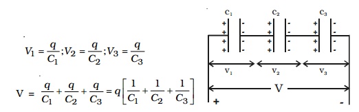
(i) Capacitors in series
Consider three capacitors of capacitance C1, C2 and C3 connected in series (Fig 1.28). Let V be the potential difference applied across the series combination. Each capacitor carries the same amount of charge q. Let V1, V2, V3 be the potential difference across the capacitors C1, C2, C3 respectively. Thus V = V1 + V2 + V3
The potential difference across each capacitor is,
If CS, be the effective capacitance of the series combination, it should acquire a charge q when a voltage V is applied across it.
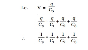
when a number of capacitors are connected in series, the reciprocal of the effective capacitance is equal to the sum of reciprocal of the capacitance of the individual capacitors.
(ii) Capacitors in parallel
Consider three capacitors of capacitances C1, C2 and C3 connected in parallel (Fig.1.29). Let this parallel combination be connected to a potential difference V. The potential difference across each capacitor is the same. The charges on the three capacitors are,
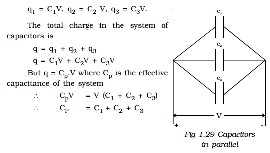
Hence the effective capacitance of the capacitors connected in parallel is the sum of the capacitances of the individual capacitors.
8. Energy stored in a capacitor
The capacitor is a charge storage device. Work has to be done to store the charges in a capacitor. This work done is stored as electrostatic potential energy in the capacitor.
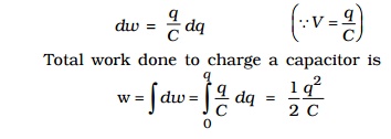
Let q be the charge and V be the potential difference between the plates of the capacitor. If dq is the additional charge given to the plate, then work done is, dw = Vdq
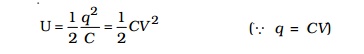
This work done is stored as electrostatic potential energy (U) in the capacitor.
This energy is recovered if the capacitor is allowed to discharge.
9. Distribution of charges on a conductor and action of points
Let us consider two conducting spheres A and B of radii r1 and r2 respectively connected to each other by a conducting wire (Fig 1.30). Let r1 be greater than r2. A charge given to the system is distributed as q1 and q2 on the surface of the spheres A and B.
Let ?1, ?2 be the charge densities on the sphere A and B.
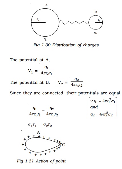
i.e., σr is a constant. From the above equation it is seen that, smaller the radius, larger is the charge density.
In case of conductor, shaped as in Fig.1.31 the distribution is not uniform. The charges accumulate to a maximum at the pointed end where the curvature is maximum or the radius is minimum. It is found experimentally that a charged conductor with sharp points on its surface, loses its charge rapidly.
The reason is that the air molecules which come in contact with the sharp points become ionized. The positive ions are repelled and the negative ions are attracted by the sharp points and the charge in them is therefore reduced.
Thus, the leakage of electric charges from the sharp points on the charged conductor is known as action of points or corona discharge. This principle is made use of in the electrostatic machines for collecting charges and in lightning arresters (conductors).
Related Topics