Chapter: Design of Electrical Machines : Transformers
Core type transformer - Design of Transformers
Core type transformer
Note:
1. D-distance between the two core or leg central lines
2. Width Ww is measured from one edge of the leg to the other of the adjacent leg in case of square or rectangular core with square or rectangular coil and between the two circumscribing circles of adjacent legs in case of stepped legs.
3. Depth or width of the core type transformer = b in case of rectangular core
= a in case of square or stepped core
Overall length = (Ww + 2a) or (D+a) in case of single phase core type transformer with square or rectangular core
= (Ww+d+a) or (D+a) in case of single phase core type transformer with a Stepped leg
= (2Ww + 2d + a) or (2D+a) in case of three phase core type transformer with a stepped leg. No square or rectangular leg is used for high capacity three phase transformers.
Overall height = (Hw + 2Hy) for all core type transformers.
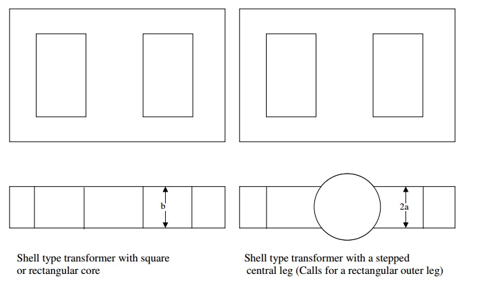
Depth or width of the Shell type transformer = b in case of rectangular central leg
= 2a in case of stepped central leg
Overall length = (2Ww + 4a) in case of a shell type transformer with rectangular or square central leg
= (d + 2Ww + 2a) in case of shell type transformer with central stepped leg
Overall height = (Hw + 2Hy) in case of a single phase shell type transformer
= 3(Hw+2Hy) in case of a three phase shell type transformer
Winding details:
Since the applied voltage V1 is approximately equal to the voltage induced E1 = 4.44 φm f T1 = Et T1
Number of primary turns (or turns / phase) T1 = V1 / Et in case of single phase transformers
= V1ph / Et in case of 3 phase transformers
Number of secondary turns (or turns / phase) T2 = V2/ Et in case of single phase transformers
= V2ph / Et in case of 3 phase transformers
Primary current (or current/phase) I1 = kVA x 103 / V1 in case of single phase transformers
= kVA x 103 / 3V1ph in case of 3 phase transformers
Cross-sectional area of primary winding conductor a1 = I1/ δ mm2
Secondary current (or current / phase) I2 = kVA x 103 / V2 in case of single phase transformers
= kVA x 103 / 3V2ph in case of 3 phase transformers
Cross-sectional area of secondary winding conductor a2 = I2/ δ mm2
Knowing the number of turns and cross-sectional area of the primary and secondary winding conductors, number of turns/layer in a window height of Hw and number of layers in a window width of Ww can be found out.
Related Topics