Chapter: Automation, Production Systems, and Computer Integrated Manufacturing : Numerical Control
Computer Numerical Control
COMPUTER NUMERICAL CONTROL
Computer Numerical Control:
a. Features of CNC
b. The Machine Control Unit for CNC
c. CNC Software
Since the introduction of NC in 1952, there have been dramatic advances in digital computer technology. The physical size and cost of 11digital computer have been significantly reduced at the same time that its computational capabilities have been substantially increased. It was logical for the makers of NC equipment to incorporate these advances in computer technology into their products, starting first with large mainframe computers in the 1960s, followed hy minicomputers in the 1970s,and microcomputers in the 1980s (Historical Note 6.2). Today, NC means computer numerical control. Computer numerical control (CNC) is defined as an NC system whose MeV is based on a dedicated microcomputer rather than on a hardwired controller.
Historical Note 6.2 Digital computers for NC
I'he development of NC has relied heavily on advances in digital computer technology. As computers evolved and their performance improved, producers of NC machines were quick to adopt the latest generation of com pUler technology, The first application of the digital computer for NC was 10 perform part programming. In 1956.MIT demonstrated the feasibility of a computeraided part programming system using its Whirlwind I computer (an early digital computer prototype developed at MIT).
Features of CNC
Computer NC systems include additional features beyond what is feasible with conventional hardwired NC. These features, many of which are standard on most CNC MCVs whereas others are optional, include rhc following'
Storage of more than one part program. With improvements in computer storage technology. newer CNC controllers have sufficient capacity to store multiple programs. Controller manufacturers generally offer one or more memory expansions as optionstothcMCU.
Variomform.l of program input. Whereas conventional (hardwired) MCVs are limited to punched tape as the input medium for entering part programs. CNC controllers generally possess multiple data entry capabilities, such as punched tape (if the machine shop still uses punched tape), magnetic tape. floppy diskette. RS232 communications with external computers, and manual data input (operator entry of program).
Program editi'll{ at the machine tool. CNC permits a part program to be edited while it resides in the MCV computer memory. Hence, the process of testing and correcting a program can be done entirely at the machine sire, rather than returning to the programming office to,correct t~e tape. In addi:ion to part ~tograrn corrections.editing also permits optimizing cuumg conditions m the machining cycle. After correcting and optimizing the program. the revised version can be stored on punched tape or other media for future usc.
Fixed cycles and programming subroutines. The increased memory capacity and the ability III I'lOgrmlllhe control cornpurer provide the opportunity 10store frequently
used machining cycles as mucros that can be called by the part program. Instead of writing the full instructions for the particular cycle into every program, a call statement is included in the part program to indicate that the macro cycle should be executed. These cycles often require that certain parameters be defined; for example. a bolt hole circle, in which the diameter ot the bolt circle, the spacing of the bolt holes, and other parameters must be specified.
Interpolation. Some of the interpolation schemes described in Table 6.1 are normally executed only on a CNC system because of the computational requirements. Linear and circular interpolation arc sometimes hardwired into the control unit, but helical, parabolic, and cubic interpolations are usually executed in a stored program algorithm.
Positioning features for setup. Setting up the machine tool for a givcn work part involves installing and aligning a fixture on the machine tool table. This must be accomplished so that the machine axes are estahlished with respect to the workpart, The alignment task can be facilitated using certain features made possible by software options in a CNC system. Position set is one of these features. With position set , the operator is not required to locate the fixture on the machine table with extreme accuracy. Instead, the machine tool axes are referenced to the location of the fixture by using a target point or set of target points on the work or fixture.
Cutter length and size compensation. In older style controls, cutter dimensions had 10 be set very precisely to agree with the tool path defined in the part program. Alternative methods for ensuring accurate tool path definition have been incorporated into CNC controls. One method involves manually entering the actual 1001dimensions into the MCU. These actual dimensions may differ from those originally programmed Compensations arc then automatically made in the computed tool path. Another method involves use of a toollcngth sensor built into the machine. In this technique. the cutter is mounted in the spindle and the sensor measures its length. This measured value is then used to correct the programmed tool path.
Acceleration and deceleration calculations, This feature is applicable when the cutter moves at high feed rates. It is designed to avoid tool marks on the work surface that would be generated due to machine tool dynamics when the cutter path changes abruptly. Instead, the feed rate is smoothly decelerated in anticipation of a tool path change and then accelerated back up to the programmed feed rate after the direction change.
Communications interface. With the trend toward interfacing and networking in plants today, most modem CNC con/rollers are equipped with a standard RS232 or other communications interface to allow the machine to be linked to other computers and computerdriven devices. This is useful for various applications, such as: (1) downloading part programs from a central data file as in distributed NC; (2) collecting operational data such as workpiece counts, cycle times, and machine utilization; and
interfacing with peripheral equipment. such as robots that load and unload parts.
Diagnostics. Many modern CNC systems possess an online diagnostics capability that monitors certain aspects of the machine tool to detect malfunctions or signs of impending malfunctions or to diagnose system breakdowns. Some of the common features of a CNC diagnostics system are listed in Table 6.2
The Machine Control Unit for CNC
The MCU is the hardware that distinguishes CNC from conventional NC. The general configuration of the MCV in a CNC system is illustrated in Figure 6.7. The MCV consists of the following components and subsystems: (I) central processing unit, (2) momery,
(3) lIO interface. (4) controls for machine tool axes and spindle speed. and (5) sequence controls for other machine tool functions. These subsystems are interconnected by means of a system bus. as indicated in the figure,
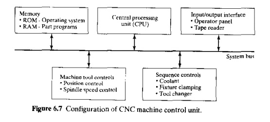
Centra! Processing Unit. The central processing unit (CPU) i~the brain of the Mev. It manages the other components in the Mel!based on software contained in main memory.Thc CPU can be divided into three sections: (1) control section, (2) arithmeticlogic unit, and (3) immediate access memory. The control section retrieves commands and data from memory and generates signals 10 activate other components in the Meu. In short, it sequences. coordinates. and regulates all of the activities of the Mrl J computer. The arithmeuciogtc unit (ALU) consists of the circuitry to perform various calculations (addition, subtraction, multiplication), counting. and logical functions required by software residing in memory. The immediate access memory provides a temporary storage for data being processed by the CPu. It is connected to main memory by means of the system data bus.
Memory. The immediate (lCCCSS memory in the CPU is not intended for storing CNC software, A much greater storage capacity is required for the various programs and data needed to operate the CNC system. As with most other computer systems, CNC memory can be divided into two categories: (I) main memory and (2) secondary memory. Main memory (also known as primary storaf;e)consists of RO\1 (readonly memory) and RAM (random access memory) devices. Operating system software and machine interface programs (Section 6.2.3) are generally stored in ROM. These programs are usually installed by the manufacturer of the MCU. Numerical control part programs are stored in RAM devices. Current programs in RAM can he erased and replaced by new programs as jobs are changed.
Highcapacity secondary memory (also called auxiliary storage or secondary storage) devices are used to store large programs and data files, which are transferred to main memory as needed. Common among the secondary memory devices are floppy diskettes and hard disks. Floppy diskettes are portable and have replaced much of the punched paper tape traditionally used 10 store part programs. Hard disks are highcapacity storage devices that are permanently installed in the CNC machine control unit. CNC secondary memory is used to store part programs, macros, and other software.
Input/Output Interface. The IIO interface provides communication between the various components of the CNC system, other computer systems. and the machine operator. As its name suggests, the 110 interface transmits and receives data and signals to and [rom external devices, several of which are indicated in Figure 6.7. The opera/or control panel is the basic interface by which the machine operator communicates to the CNC system. This is used to enter commands relating to part program editing, MeU operating mode (e.g .. program control vs. manual control),speeds and feeds, cutrtng fluid pump onloff, and similar functions. Either an alphanumeric keypad or keyboard is usuallv included in the operator control panel. The 110interface also includes a display (CRT orLED) for corn~unication o.fdata and information from the MCV to the machine operator. The display IS used to indicate current status of the program as it is being executed and to warn the operator of any malfunctions in the CNC system.
Also included in the 110 interrace are one or more means of entering the part program into storage. As indicated previously, NC part programs are stored in a variety of ways, including punched tape. magnetic tape, and floppy disks. Programs can also be entered manually by the machine operator or stored at a central computer site and transmitted via loea! area nl'T~'nrk (LAN) to the CNCsystem',Whichevcr mcans.isemployed by the plant, a suitable device must be included in the J/O interface 10 allow input of the program into MCU memory.
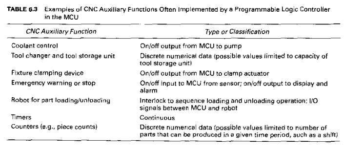
Sequence Controls for Other Machine Tool Functions. In addition to control of table position. feed rate. and spindle speed, several additional functions arc accomplished under pan program control.These auxiliary functions arc generally on/off (binary] actuations. interlocks. and discrete numerical data. A sampling of these functions is presented in Table 0.3. To avoid overloading the CPU, a prograrnrnable logic controller (Chapter H) is sometimes used to manage the 110 interface for these auxiliary functions
Personal Computers and the MCV. In growing numbers, personal computers (PCs) are being used in the factory to implement process control (Section 4.4.6), and CNC is no exception. Tho basic configurations are being applied [14J: (1) the PC is used as a separate frontend interface for the MCU, and (2) the PC contains the motion control board and other hardware required to operate the machine tool. In the second case, the CNC control board fits into a standard slot of the P'C. In either configuration, the advantage of using a PC for CNC is its flexibility to execute a variety of user software in addition
to and concurrently with controlling the machine tool operation. The user software might include programs for shopflour control. statistical process control, solid modeling,cutting tool management, and other computeraided manufacturing software. Other benefits include improved case of use compared with conventional CNC and ease of networking the PCs, Possible disadvantages include (1) lost time to retrofit the PC for OK. particularly when installing the rNr motion controls inside the PC and (2) current limitations in applications requinng complex fiveaxis control of the machine toolfor these application>, traditional CNC is still more efficient. II should he mentioned that advances in the technology of PCbased CNC are likely to reduce these disadvantages over time. Companies are demanding open architecture in CNC products, which permits components from different vendors to be used in the same system [7J
CNC Software
The computer in CNC operates by means of software. There are three types of software programs used in CNC systems: (I) operating system software, (2) machine interface software, and (3) application software.
The principal function of the operating system software is to interpret the NC part pro
grams and generate the corresponding control signals to drive the machine tool axes. It is installed by the controller rnanuracturer and is stored in ROM in the MCU. The operating
system software consists of the following: (1) an editor, which permits the machine operator to input and edit NC part programs and perform other file management functions: (2) a control program, which decodes the part program instructions, performs interpolation and acceleration/deceleration calculations, and accomplishes other related functions to produce the coordinate control signals for each axis.and (3) an executive program, which manages the execution of the CNC software as well as the 1/0 operations of the Mev. The operating system software also includes the diagnostics routines that are available in the CNC svstem (Table 6.2).
The machine interface software is used to operate the communication link between the CPU and the machine tool to accomplish the CNC auxiliary functions (Table 6.3).As previously indicated, the I/O signals associated with the auxiliary functions arc sometimes im
plemented by means of a programmable logic controller interfaced to the MCU,and so the machine interface software is often written in tbe form of ladder logic diagrams (Section 8.2).
Finally, the application software consists of the NC part programs that are written for machining (or other) applications in the user's plant. We postpone the topic of part programming to Section 6.5.
Related Topics