Chapter: Digital Principles and System Design : Boolean Algebra and Logic Gates
Boolean Algebra and Logic Gates
BOOLEAN ALGEBRA AND
MINIMIZATION
1 Introduction:
The English
mathematician George Boole (1815-1864) sought to give symbolic form to Aristotle‘s
system of logic. Boole wrote a treatise on the subject in 1854, titled An
Investigation of the Laws of Thought, on Which Are Founded the Mathematical
Theories of Logic and Probabilities, which codified several rules of
relationship between mathematical quantities limited to one of two possible
values: true or false, 1 or 0. His mathematical system became known as Boolean
algebra.
All arithmetic operations performed with Boolean quantities have but one of two possible Outcomes: either 1 or 0. There is no such thing as .2. or .-1. or .1/2. in the Boolean world. It is a world in which all other possibilities are invalid by fiat. As one might guess, this is not the kind of math you want to use when balancing a checkbook or calculating current through a resistor.
However, Claude Shannon of MIT fame
recognized how Boolean algebra could be applied to on-and-off circuits, where
all signals are characterized as either .high. (1) or .low. (0). His1938 thesis,
titled A Symbolic Analysis of Relay and Switching Circuits, put Boole‘s theoretical
work to use in a way Boole never could have imagined, giving us a powerful
mathematical tool for designing and analyzing digital circuits.
Like .normal. algebra,
Boolean algebra uses alphabetical letters to denote variables. Unlike .normal.
algebra, though, Boolean variables are always CAPITAL letters, never lowercase.
Because they are allowed to possess only
one of two possible values, either 1 or 0, each and every variable has a
complement: the opposite of its value. For example, if variable .A. has a value
of 0, then the complement of A has a value of 1. Boolean notation uses a bar
above the variable character to denote complementation, like this:
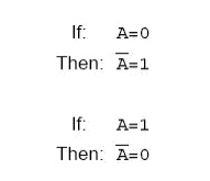
In
written form, the complement of .A. denoted as .A-not. or .A-bar.. Sometimes a
.prime.symbol is used to represent complementation. For example, A‘ would be
the complement of A, much the same as using a prime symbol to denote
differentiation in calculus rather than the fractional notation dot. Usually,
though, the .bar. symbol finds more widespread use than the .prime. symbol, for
reasons that will become more apparent later in this chapter.
2
Boolean Arithmetic:
Let us begin our exploration of Boolean
algebra by adding numbers together:
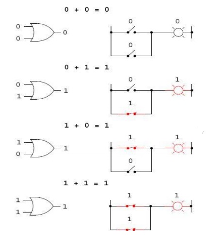
0 + 0 = 0
0 + 1 = 1
1 + 0 = 1
1 + 1 = 1
The first three sums
make perfect sense to anyone familiar with elementary addition. The Last sum,
though, is quite possibly responsible for more confusion than any other single
statement in digital electronics, because it seems to run contrary to the basic
principles of mathematics.
Well, it does contradict principles of
addition for real numbers, but not for Boolean numbers. Remember that in the
world of Boolean algebra, there are only two possible values for any quantity
and for any arithmetic operation: 1 or 0. There is no such thing as .2. within
the scope of Boolean values. Since the
sum .1 + 1. certainly isn‘t 0, it must be 1 by process of elimination.
2.1
Addition – OR Gate Logic:
Boolean addition
corresponds to the logical function of an ||OR|| gate, as well as to parallel
switch contacts:
There
is no such thing as subtraction in the realm of Boolean mathematics.
Subtraction Implies the existence of
negative numbers: 5 - 3 is the same thing as 5 + (-3), and in Boolean algebra
negative quantities are forbidden. There is no such thing as division in
Boolean mathematics, either, since division is really nothing more than
compounded subtraction, in the same way that multiplication is compounded
addition.
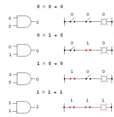
2.2
Multiplication – AND Gate logic
Multiplication is valid
in Boolean algebra, and thankfully it is the same as in real-number algebra:
anything multiplied by 0 is 0, and anything multiplied by 1 remains unchanged:
0 × 0 = 0
0 × 1 = 0
1 × 0 = 0
1 × 1 = 1
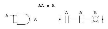
This set of equations should also look
familiar to you: it is the same pattern found in the truth table for an AND gate. In other words, Boolean
multiplication corresponds to the logical function of an .AND. gate, as well as to
series switch contacts:
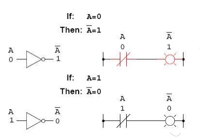
2.3
Complementary Function – NOT gate Logic
Boolean complementation finds
equivalency in the form of the NOT gate, or a normally closed switch or relay
contact:
3
Boolean Algebraic Identities
In mathematics, an
identity is a statement true for all possible values of its variable or variables. The algebraic identity of x + 0 = x
tells us that anything (x) added to zero equals the original .anything,. no
matter what value that .anything. (x) may be. Like ordinary algebra, Boolean
algebra has its own unique identities based on the bivalent states of Boolean
variables.
The first Boolean identity is that the sum of
anything and zero is the same as the original .anything.. This identity is no
different from its real-number algebraic equivalent:
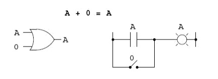
No matter what the value of A, the
output will always be the same: when A=1, the output will also be 1; when A=0,
the output will also be 0.
The next identity is most definitely
different from any seen in normal algebra. Here
we discover that the sum of anything and
one is one:
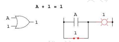
No matter what the value of A, the sum
of A and 1 will always be 1. In a sense, the 1 signal overrides the effect of A
on the logic circuit, leaving the output fixed at a logic level of 1. Next, we
examine the effect of adding A and A together, which is the same as connecting
both inputs of an OR gate to each other and activating them with the same
signal:
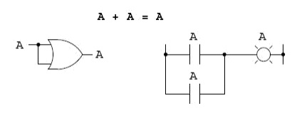
In real-number algebra, the sum of two
identical variables is twice the original variable‘s value (x + x = 2x), but remember that there is
no concept of .2. in the world of Boolean math, only 1 and 0, so we cannot say
that A + A = 2A. Thus, when we add a Boolean quantity to itself, the sum is equal to the original quantity: 0 +
0 = 0, and 1 + 1 = 1.
Introducing the uniquely Boolean concept
of complementation into an additive identity, we find an interesting effect.
Since there must be one .1. value between any variable and its complement, and since the sum of any Boolean quantity and
1 is 1, the sum of a variable and its complement must be 1:

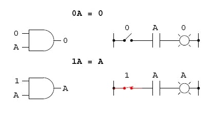
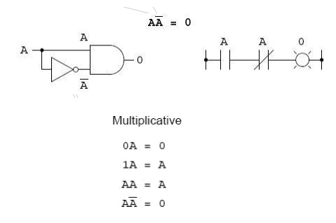
Four multiplicative
identities: Ax0, Ax1, AxA, and AxA‘. Of these, the first two are no different
from their equivalent expressions in regular algebra:
The third
multiplicative identity expresses the result of a Boolean quantity multiplied
by s itself. In normal algebra, the product of a variable and itself is the
square of that variable (3x 3 =32 = 9). However, the concept of .square. implies
a quantity of 2, which has no meaning in Boolean algebra, so we cannot say that
A x A = A2. Instead, we find that the product of a Boolean quantity and itself
is the original quantity, since 0 x 0 = 0 and 1 x 1 = 1:
The fourth multiplicative
identity has no equivalent in regular algebra because it uses the complement of
a variable, a concept unique to Boolean mathematics. Since there must be one
.0. value between any variable and its complement, and since the product of any
Boolean quantity and 0 is 0, the product of a variable and its complement must
be 0:
4 Principle of Duality:
It states that every algebraic expression is
deducible from the postulates of Boolean algebra, and it remains valid if the
operators & identity elements are interchanged. If the inputs of a NOR gate
are inverted we get a AND equivalent circuit. Similarly when the inputs of a
NAND gate are inverted, we get a OR equivalent circuit. This property is called
DUALITY.
5 Theorems of Boolean algebra:
The theorems of Boolean
algebra can be used to simplify many a complex Boolean
expression and also to
transform the given expression into a more useful and meaningful equivalent
expression. The theorems are presented as pairs, with the two theorems in a
given pair being the dual of each other. These theorems can be very easily
verified by the method of =perfect induction‘. According to this method, the
validity of the expression is tested for all possible combinations of values of
the variables involved. Also, since the validity of the theorem
is based on its being
true for all possible combinations of values of variables, there is no reason
why a variable cannot be replaced with its complement, or vice versa, without
disturbing the validity. Another important point is that, if a given expression
is valid, its dual will also be valid
5.1 Theorem 1 (Operations with =0‘ and =1‘)
(a) 0.X = 0 and (b)
1+X= 1
Where X is not
necessarily a single variable – it could be a term or even a large expression.
Theorem 1(a) can be proved by substituting all possible values of X, that is, 0
and 1, into the given expression and checking whether the LHS equals the RHS:
• For X = 0, LHS = 0.X
= 0.0 = 0 = RHS.
• For X= 1, LHS = 0.1 =
0 = RHS.
Thus, 0.X =0 irrespective
of the value of X, and hence the proof.
Theorem 1(b) can be
proved in a similar manner. In general, according to theorem 1, 0. (Boolean
expression) = 0 and 1+ (Boolean expression) =1.
For example: 0.
(A.B+B.C +C.D) = 0 and 1+ (A.B+B.C +C.D) = 1, where A, B and C are Boolean
variables.
5.2 Theorem 2 (Operations with =0‘ and =1‘)
(a) 1.X = X and (b) 0+X
= X
where X could be a
variable, a term or even a large expression. According to this theorem, AND ing
a Boolean expression to =1‘ or ORing =0‘ to it makes no difference to the
expression:
• For X = 0, LHS = 1.0
= 0 = RHS.
• For X = 1, LHS = 1.1
= 1 = RHS.
Also,
1. (Boolean expression)
= Boolean expression and 0 + (Boolean expression) = Boolean expression.
For example,
1.(A+B.C +C.D) = 0+(A+B.C
+C.D) = A+B.C +C.D
5.3 Theorem 3 (Idempotent or Identity Laws)
(a) X.X.X……X = X and
(b) X+X+X +···+X = X
Theorems 3(a) and (b)
are known by the name of idempotent laws, also known as identity laws. Theorem
3(a) is a direct outcome of an AND gate operation, whereas theorem 3(b)
represents an OR gate operation when all the inputs of the gate have been tied
together. The scope of idempotent laws can be expanded further by considering X
to be a term or an expression. For
example, let us apply
idempotent laws to simplify the following Boolean expression:
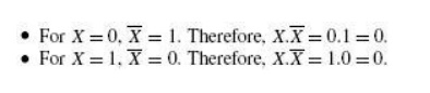
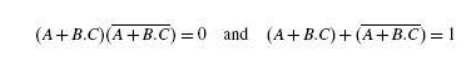
5.4 Theorem 4 (Complementation Law)
(a) X-X = 0 and (b) X+X = 1
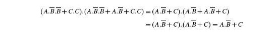
According to this
theorem, in general, any Boolean expression when ANDed to its complement yields
a =0‘ and when ORed to its complement yields a =1‘, irrespective of the
complexity of the expression:
Hence, theorem 4(a) is
proved. Since theorem 4(b) is the dual of theorem 4(a), its proof is implied.
The example below further illustrates the application of complementation laws:
5.5 Theorem 5 (Commutative property)
Mathematical identity, called a .property. or
a .law,. describes how differing
variables relate to
each other in a system of numbers. One of these properties is known as the
commutative property, and it applies equally to addition and multiplication. In
essence, the commutative property tells
us we can reverse the order of variables that are either added together or
multiplied together without changing the truth of the expression:
Commutative property of
addition
A + B = B + A
Commutative property of
multiplication
AB = BA
5.6 Theorem 6 (Associative Property)
The Associative
Property, again applying equally well to addition and multiplication.This
property tells us we can associate groups of added or multiplied variables
together with parentheses without altering the truth of the equations.
Associative property of
addition
A + (B + C) = (A + B) +
C
Associative property of
multiplication
A (BC) = (AB) C
5.7 Theorem 7 (Distributive Property)
The Distributive Property, illustrating how to
expand a Boolean expression formed by theproduct of a sum, and in reverse shows
us how terms may be factored out of Boolean sums-of-products:
Distributive property
A (B + C) = AB + AC
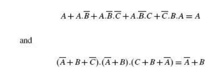
5.8 Theorem 8 (Absorption Law or Redundancy Law)
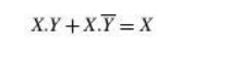
(a) X+X.Y = X and (b)
X.(X+Y) = X
The proof of absorption
law is straightforward:
X+X.Y = X. (1+Y) = X.1
= X
Theorem 8(b) is the
dual of theorem 8(a) and hence stands proved.
The crux of this
simplification theorem is that, if a smaller term appears in a larger term,
then the larger term is redundant. The following examples further illustrate
the underlying concept:
5.9 Demorgan‘s Theorem
De-Morgan was a great logician and
mathematician. He had contributed much to logic.
Among his contribution
the following two theorems are important
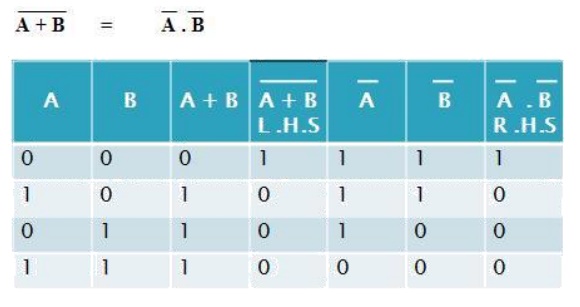
5.9.1 De-Morgan‘s First Theorem
It States that .The complement of the sum of
the variables is equal to the product of the complement of each variable.. This
theorem may be expressed by the following Boolean expression.
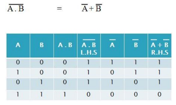
5.9.2 De-Morgan‘s Second Theorem
It states that the
.Complement of the product of variables is equal to the sum of complements of
each individual variables.. Boolean expression for this theorem is
1.6 Boolean function
Z=AB‘+A‘C+A‘B‘C‘
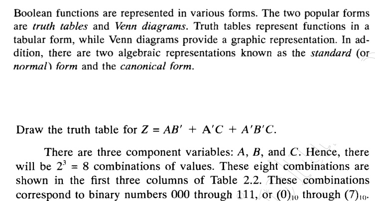
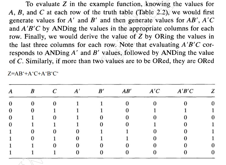
7 Canonical Form of Boolean Expressions
An expanded form of Boolean expression, where
each term contains all Boolean variables in their true or complemented form, is
also known as the canonical form of the expression. As an illustration, is a
Boolean function of three variables expressed in canonical form. This function
after simplification reduces to and loses its canonical form.
7.1 MIN TERMS AND MAX TERMS
Any boolean expression may be expressed in
terms of either minterms or maxterms. To do this we must first define the
concept of a literal. A literal is a single variable within a term which may or
may not be complemented. For an expression with N variables, minterms and
maxterms are defined as follows :
• A minterm is the
product of N distinct literals where each literal occurs exactly once.
• A maxterm is the sum
of N distinct literals where each literal occurs exactly
once. Product-of-Sums
Expressions
7.2 Standard Forms
A product-of-sums expression contains the
product of different terms, with each term being either a single literal or a
sum of more than one literal. It can be obtained from the truth table by
considering those input combinations that produce a logic =0‘ at the output.
Each such input combination gives a term, and the product of all such terms
gives the expression. Different terms are obtained by taking the sum of the
corresponding literals. Here, =0‘ and =1‘ respectively
mean the uncomplemented
and complemented variables, unlike sum-of-products expressions where =0‘ and
=1‘ respectively mean complemented and uncomplemented variables.
Since each term in the
case of the product-of-sums expression is going to be the sum of literals, this
implies that it is going to be implemented using an OR operation. Now, an OR
gate produces a logic =0‘ only when all its inputs are in the logic =0‘ state,
which means that the first term corresponding to the second row of the truth
table will be A+B+C. The product-of-sums Boolean expression for this truth
table is given by Transforming the given product-of-sums expression
into an equivalent
sum-of-products expression is a straightforward process. Multiplying out the
given expression and carrying out the obvious simplification provides the
equivalent sum-of-products expression:
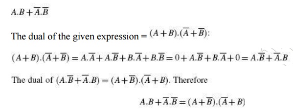
A given sum-of-products expression can be transformed into an equivalent product-of-sums expression by (a) taking the dual of the given expression, (b) multiplying out different terms to get the sum-of products form, (c) removing redundancy and (d) taking a dual to get the equivalent product-of-sums expression. As an illustration, let us find the equivalent product-of-sums expression of the sum-of products expression The dual of the given expression =
8 Minimization Technique
The
primary objective of all simplification procedures is to obtain an expression
that has the minimum number of terms. Obtaining an expression with the minimum
number of literals is usually the secondary objective. If there is more than
one possible solution with the same number of terms, the one having the minimum
number of literals is the choice.
There are several
methods for simplification of Boolean logic expressions. The process is usually
called logic minimization. and the goal is to form a result which is efficient.
Two methods we will discuss are algebraic minimization and Karnaugh maps. For
very complicated problems the former method can be done using special software
analysis programs. Karnaugh maps are also limited to problems with up to 4
binary inputs. The Quine–McCluskey tabular method is used for more than 4
binary inputs.
9 Karnaugh Map Method
Maurice Karnaugh, a
telecommunications engineer, developed the Karnaugh map at Bell Labs in 1953
while designing digital logic based telephone switching circuits.Karnaugh maps
reduce logic functions more quickly and easily compared to Boolean algebra. By
reduce we mean simplify, reducing the number of gates and inputs. We like to
simplify logic to a lowest cost form to save costs by elimination of
components. We define lowest cost as being the lowest number of gates with the
lowest number of inputs per gate.
A Karnaugh map is a graphical representation
of the logic system. It can be drawn directly from either minterm
(sum-of-products) or maxterm (product-of-sums) Boolean expressions. Drawing a
Karnaugh map from the truth table involves an additional step of writing the
minterm or maxterm expression depending upon whether it is desired to have a
minimized sum-of-products or a minimized product of-sums expression.
9.1 Construction of a Karnaugh Map
An n-variable Karnaugh map has 2n squares, and
each possible input is allotted a square. In the case of a minterm Karnaugh
map, =1‘ is placed in all those squares for which the output is =1‘, and =0‘ is
placed in all those squares for which the output is =0‘. 0s are omitted for
simplicity. An =X‘ is placed in squares corresponding to =don‘t care‘
conditions. In the case of a maxterm Karnaugh map, a =1‘ is placed in all those
squares for which the output is =0‘, and a =0‘ is placed for input entries
corresponding to a =1‘ output. Again, 0s are omitted for simplicity, and an =X‘
is placed in squares corresponding to =don‘t care‘ conditions. The choice of
terms identifying different rows and columns of a Karnaugh map is not unique
for a given number of variables. The only condition to be satisfied is that the
designation of adjacent rows and adjacent columns should be the same except for
one of the literals being complemented. Also, the extreme rows and extreme
columns are considered adjacent.
Some of the possible designation styles for
two-, three- and four-variable minterm Karnaugh maps are shown in the figure
below.
The style of row
identification need not be the same as that of column identification as long as
it meets the basic requirement with respect to adjacent terms. It is, however,
accepted practice to adopt a uniform style of row and column identification.
Also, the style shown in the figure below is more commonly used. A similar
discussion applies for maxterm Karnaugh maps. Having drawn the Karnaugh map,
the next step is to form groups of 1s as per the following guidelines:
1. Each square containing a =1‘ must be
considered at least once, although it can be considered as often as desired.
2. The objective should
be to account for all the marked squares in the minimum number of groups.
3. The number of
squares in a group must always be a power of 2, i.e. groups can have 1,2, 4, 8,
16, squares.
4. Each group should be
as large as possible, which means that a square should not be accounted for by
itself if it can be accounted for by a group of two squares; a group of two
squares should not be made if the involved squares can be included in a group
of four squares and so on.
5. =Don‘t care‘ entries
can be used in accounting for all of 1-squares to make optimum groups. They are
marked =X‘ in the corresponding squares. It is, however, not necessary to
account for all =don‘t care‘ entries. Only such entries that can be used to advantage
should be used.
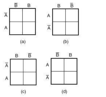
Fig 1.9.1 Two variable
K Map
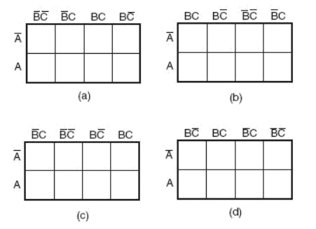
Fig 1.9.2 Three
variable K Map

Fig 1.9.3 Four variable
K Map

Fig 1.9.4 Different
Styles of row and column identification
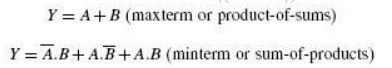
Having accounted for groups with all 1s, the
minimum =sum-of-products‘ or =product-of-sums‘ expressions can be written
directly from the Karnaugh map. Minterm Karnaugh map and Maxterm Karnaugh map
of the Boolean function of a two-input OR gate. The Minterm and Maxterm Boolean
expressions for the two-input OR gate are as follows:
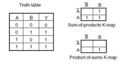
Minterm Karnaugh map and Maxterm Karnaugh map of the three variable
Boolean function
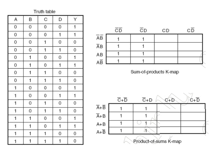
The truth table,
Minterm Karnaugh map and Maxterm Karnaugh map of the four
variable Boolean
function
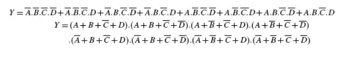
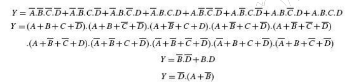
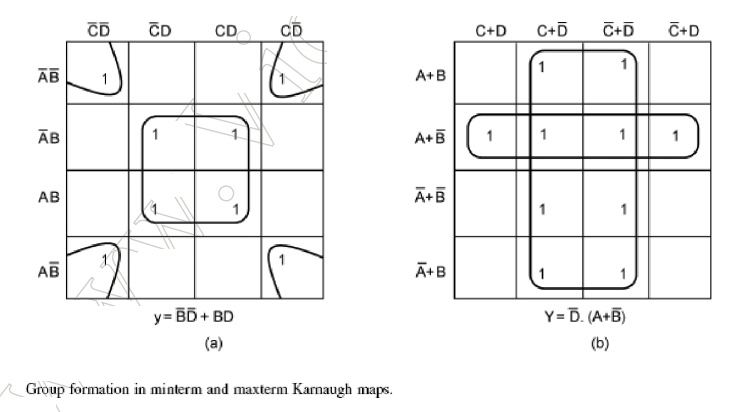
To illustrate the
process of forming groups and then writing the corresponding minimized Boolean
expression, The below figures respectively show minterm and maxterm Karnaugh
maps for the Boolean functions expressed by the below equations. The minimized
expressions as deduced from Karnaugh maps in the two cases are given by
Equation in the case of the minterm Karnaugh map and Equation in the case of
the maxterm Karnaugh map:
10 Quine–McCluskey Tabular Method
The Quine–McCluskey tabular method of simplification is based on the complementation theorem, which says that
where X
represents either a variable or a term or an expression and Y is a variable.
This theorem implies that, if a Boolean expression contains two terms that
differ only in one variable, then they can be combined together and replaced
with a term that is smaller by one literal. The same procedure is applied for
the other pairs of terms wherever such a reduction is possible. All these terms
reduced by one literal are further examined to see if they can be reduced
further. The process continues until the terms become irreducible. The
irreducible terms are called prime implicants. An optimum set of prime
implicants that can account for all the original terms then constitutes the
minimized expression. The technique can be applied equally well for minimizing
sum-of-products and product of- sums expressions and is particularly useful for
Boolean functions having more than six variables as it can be mechanized and
run on a computer. On the other hand, the Karnaugh mapping method, to be
discussed later, is a graphical method and becomes very cumbersome when the number
of variables exceeds six. The step-by-step procedure for application of the
tabular method for minimizing Boolean expressions,both sum-of-products and
product-of-sums, is outlined as follows:
1. The Boolean
expression to be simplified is expanded if it is not in expanded form.
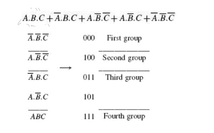
2. Different terms in
the expression are divided into groups depending upon the number of 1s they
have.
True and complemented variables in a
sum-of-products expression mean =1‘ and =0‘ respectively.
The reverse is true in the case of a
product-of-sums expression. The groups are then arranged, beginning with the
group having the least number of 1s in its included terms. Terms within the
same group are arranged in ascending order of the decimal numbers represented
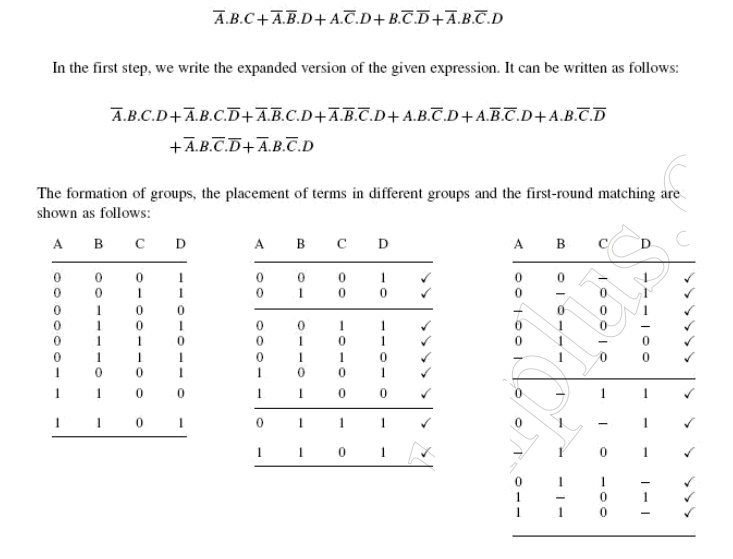
by these terms. As an illustration, consider the expression
As another illustration, consider a
product-of-sums expression given by
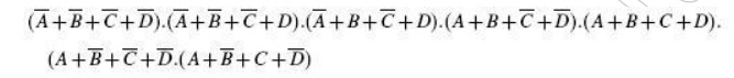
The formation of groups
and the arrangement of terms within different groups for the product-of sums
expression are as follows:
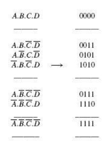
It may be mentioned
here that the Boolean expressions that we have considered above did not contain
any optional terms. If there are any, they are also considered while forming
groups. This completes the first table.
3. The terms of the
first group are successively matched with those in the next adjacent higher
order group to look for any possible matching and consequent reduction. The
terms are considered matched when all literals except for one match. The pairs
of matched terms are replaced with a single term where the position of the
unmatched literals is replaced with a dash (—). These new terms formed as a
result of the matching process find a place in the second table. The terms in
the first table that do not find a match are called the prime implicants and
are marked with an asterisk (*). The matched terms are ticked (_).
4. Terms in the second
group are compared with those in the third group to look for a possible match.
Again, terms in the second group that do not find a match become the prime
implicants.
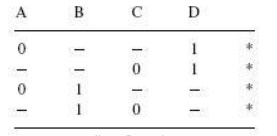
5. The process continues until we reach the
last group. This completes the first round of matching. The terms resulting
from the matching in the first round are recorded in the second table.
6. The next step is to perform matching
operations in the second table. While comparing the terms for a match, it is
important that a dash (—) is also treated like any other literal, that is, the
dash signs also need to match. The process continues on to the third table, the
fourth table and so on until the terms become irreducible any further.
7. An optimum selection
of prime implicants to account for all the original terms constitutes the terms
for the minimized expression. Although optional (also called =don‘t care‘)
terms are considered for matching, they do not have to be accounted for once
prime implicants have been identified.
Let us consider an
example. Consider the following sum-of-products expression:
The second round of
matching begins with the table shown on the previous page.
Each term in the first
group is compared with every term in the second group. For instance, the first
term in the first group 00-1 matches with the second term in the second group
01-1 to yield 0--1, which is recorded in the table shown below. The process continues
until all terms have been compared for a possible match. Since this new table
has only one group, the terms contained therein are all prime implicants. In
the present example, the terms in the first and second tables have all found a
match. But that is not always the case.
The next table is what
is known as the prime implicant table. The prime implicant table contains all
the original terms in different columns and all the prime implicants recorded
in different rows as shown below:
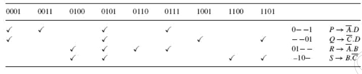
Each prime implicant is
identified by a letter. Each prime implicant is then examined one by one and
the terms it can account for are ticked as shown. The next step is to write a
product-of-sums expression using the prime implicants to account for all the
terms. In the present illustration, it is given as follows.
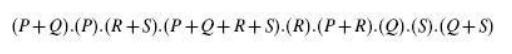
Obvious simplification reduces this expression
to PQRS which can be interpreted to mean that all prime implicants, that is, P,
Q, R and S, are needed to account for all the original terms.
Therefore, the
minimized expression = 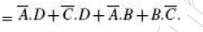
What has been described
above is the formal method of determining the optimum set of prime implicants.
In most of the cases where the prime implicant table is not too complex, the
exercise can be done even intuitively. The exercise begins with identification
of those terms that can be accounted for by only a single prime implicant. In
the present example, 0011, 0110, 1001 and 1100 are such terms. As a result, P,
Q, R and S become the essential prime implicants. The next step is to find out
if any terms have not been covered by the essential prime implicants. In the
present case, all terms
have been covered by essential prime implicants. In fact, all prime implicants
are essential prime implicants in the present example. As another illustration,
let us consider a product-of-sums expression given by

The procedure is similar to that described for
the case of simplification of sum-of-products expressions.
The resulting tables
leading to identification of prime implicants are as follows:
The prime implicant
table is constructed after all prime implicants have been identified to look
for the optimum set of prime implicants needed to account for all the original
terms. The prime implicant table shows that both the prime implicants are the
essential ones:
11 Universal Gates
OR, AND and NOT gates are the three basic
logic gates as they together can be used to construct the logic circuit for any
given Boolean expression. NOR and NAND gates have the property that they
individually can be used to hardware-implement a logic circuit corresponding to
any given Boolean expression. That is, it is possible to use either only NAND
gates or only NOR gates to implement any Boolean expression. This is so because
a combination of NAND gates or a combination of NOR gates can be used to
perform functions of any of the basic logic gates. It is for this reason that
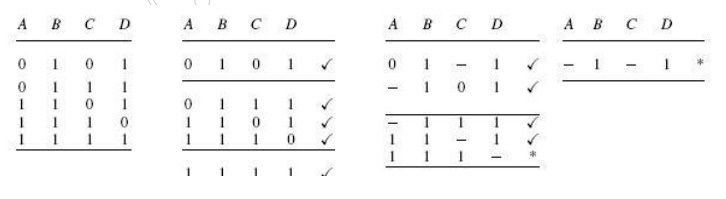
NAND and NOR gates are universal gates. As an illustration, Fig. 4.24 shows how
two-input NAND gates can be used to construct a NOT circuit, a two-input AND
gate and a two-input OR gate. Figure
shows the same using
NOR gates. Understanding the conversion of NAND to OR and NOR to AND requires
the use of DeMorgan‘s theorem, which is discussed in Chapter 6 on Boolean
algebra.
These are gates where
we need to connect an external resistor, called the pull-up resistor, between
the output and the DC power supply to make the logic gate perform the intended
logic function. Depending on the logic family used to construct the logic gate,
they are referred to as gates with open collector output (in the case of the
TTL logic family) or open drain output (in the case of the MOS logic family).
Logic families are discussed in detail in Chapter 5. The advantage of using
open collector/open drain gates lies in their capability of providing an
ANDing operation when
outputs of several gates are tied together through a common pull-up resistor,
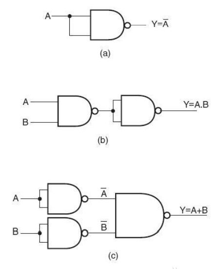
Fig 1.11.1
Implementation of basic logic gates using only NAND gates
without having to use
an AND gate for the purpose. This connection is also referred to as WIRE-AND
connection. Figure shows such a connection for open collector NAND gates. The
output in this case would be
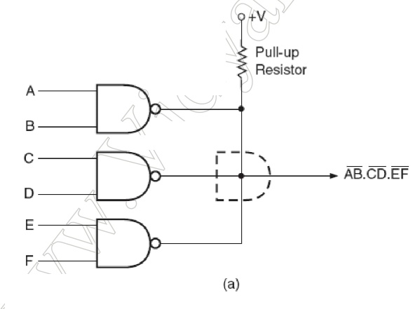
WIRE-AND connection
with open collector/drain devices.
The disadvantage is
that they are relatively slower and noisier. Open collector/drain devices are
therefore not recommended for applications where speed is an important
consideration.
The Exclusive-OR function
One element conspicuously
missing from the set of Boolean operations is that of Exclusive-OR. Whereas the
OR function is equivalent to Boolean addition, the AND function to Boolean
multiplication, and the NOT function (inverter) to Boolean complementation,
there is no direct Boolean equivalent for Exclusive-OR. This hasn‘t stopped
people from developing a symbol to represent it, though:
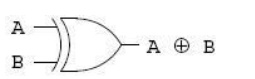
This symbol is seldom used in Boolean expressions because the identities, laws, and rules of simplification involving addition, multiplication, and complementation do not apply to it. However, there is a way to represent the Exclusive-OR function in terms of OR and AND, as has been shown in previous chapters: AB‘ + A‘B.
Related Topics