Chapter: Digital Principles and System Design : Boolean Algebra and Logic Gates
Karnaugh Maps
KARNAUGH MAPS
Maurice Karnaugh, a telecommunications engineer, developed the
Karnaugh map at Bell Labs in 1953 while designing digital logic based telephone
switching circuits. Karnaugh maps reduce logic functions more quickly and
easily compared to Boolean algebra.
A Karnaugh
map provides a pictorial method of grouping together expressions with
common factors and therefore eliminating unwanted variables. The
Karnaugh map can also be described as a
special arrangement of a truth table.
Construction
of a Karnaugh Map
1. Each
square containing a ‗1‘ must be consideredstonce,at leaalthough it can be
considered as often as desired.
2. The
objective should be to account for all the marked squares in the minimum number
of groups.
3. The
number of squares in a group must always be a power of 2, i.e. groups can have
1, 2, 4_ 8, 16, squares.
4. Each
group should be as large as possible, which means that a square should not be
accounted for by itself if it can be accounted for by a group of two squares; a
group of two squares should not be made if the
involved squares can be included in a group of four squares and so on.
5. 'Don‘t care‘ entries can be used in accountinglof-squares1foralto make optimum groups.
They are marked ‗X‘ in the rrespondingco squares.
It is, however, not necessary to account for
all 'don‘t care‘ entries. Only such entries that can be
used to advantage should be used.
The diagram below illustrates the correspondence between the Karnaugh map and the truth table for the general case of a two variable problem.
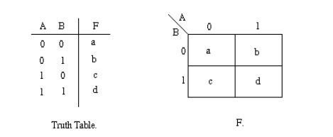
The values inside the squares are copied from the output
column of the truth table, therefore there is one square in the map for every
row in the truth table. Around the edge of the Karnaugh map are the values of
the two input variable. A is along the top and B is down the left hand side.
The diagram below explains this:
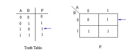
The values around the edge of the map can be thought of as
coordinates. So as an example, the square on the top right hand corner of the
map in the above diagram has coordinates A=1 and B=0. This square corresponds
to the row in the truth table where A=1 and B=0 and F=1. Note that the value in
the F column represents a particular function to which the Karnaugh map
corresponds.
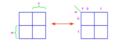
Two variable K-map
There are four minterms for two variables: hence, the map
consists of four squares, one for each minterm. In any K-Map, each square
represents a minterm. Adjacent squares always differ by just one literal (So
that the unifying theorem may apply: X + X' = 1). For the 2-variable case
(e.g.: variables X, Y), the map can be drawn as below. Two variable map is the
one which has got only two variables as input.
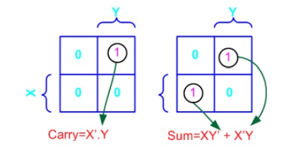
Example- Carry and Sum of a half adder
In this example we have the truth table as input, and we have
two output functions. Generally we may have n output functions for m input variables.
Since we have two output functions, we need to draw two k-maps (i.e. one for
each function). Truth table of 1 bit adder is shown below. Draw the k-map for
Carry and Sum as shown below.
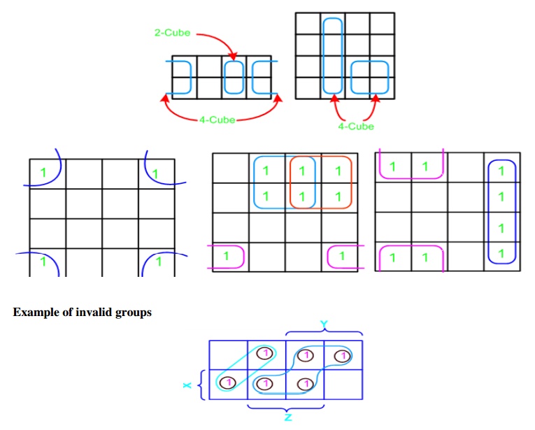
Grouping/Circling K-maps
The power of K-maps is in
minimizing the terms, K-maps can be minimized with the help of grouping the
terms to form single terms. When forming groups of squares, observe/consider
the following:
•
Every square containing 1 must be considered at
least once.
•
A square containing 1 can be included in as many
groups as desired.
•
A group must be as large as possible.
•
If a square containing 1 cannot be placed in a
group, then leave it out to include in final expression.
•
The number of squares in a group must be equal to
2 .i.e. 2,4,8,.
• The map
is considered to be folded or spherical, therefore squares at the end of a row
or column are treated as adjacent squares.
• The
simplified logic expression obtained from a K-map is not always unique.
Groupings can be made in different ways.
•
Before drawing a K-map the logic expression must
be in canonical form.
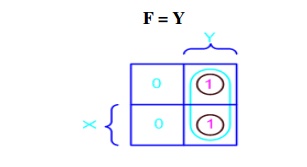
Example (1)- X'Y+XY: In this
example we have the equation as input, and we have one output function. Draw
the k-map for function F with marking 1 for X'Y and XY position. Now combine
two 1's as shown in figure to form the single term. As you can see X and X' get
canceled and only Y remains
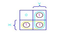
Example (2)- X'Y+XY+XY' :In this
example we have the equation as input, and we have one output function.
Draw the k-map for function F with marking 1 for X'Y, XY and XY position. Now
combine two 1's as shown in figure to form the two single terms.
F = X + Y
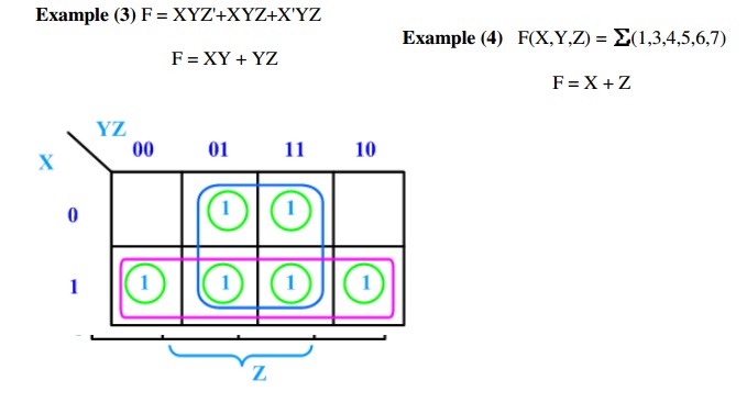
3-Variable K-Map
There are 8 minterms for 3 variables (X, Y, Z). Therefore,
there are 8 cells in a 3-variable K-map. One important thing to note is that
K-maps follow the gray code sequence, not the binary one. Each cell in a
3-variable K-map has 3 adjacent neighbours. In general, each cell in an
n-variable K-map has n adjacent neighbours.
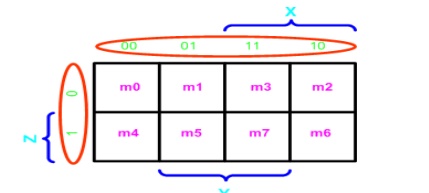
There is wrap-around in the K-map
•
X'Y'Z' (m0) is adjacent to X'YZ' (m2)
•
XY'Z' (m4) is adjacent to XYZ' (m6)
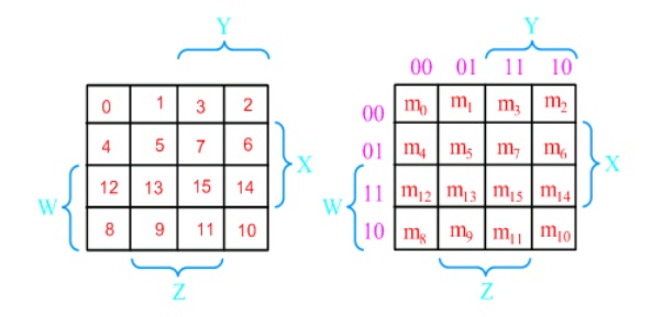
4-Variable K-Map: There are
16 cells in a 4-variable (W, X, Y, Z); K-map as shown in the figure below
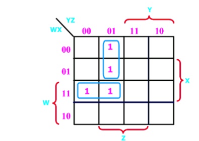
Example (5) F(W,X,Y,Z) = (1,5,12,13)
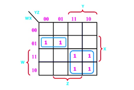
Example (6) F(W,X,Y,Z) = (4, 5, 10,
11, 14,15)
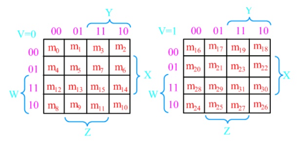
5-Variable K-Map: There are 32 cells in a
5-variable (V, W, X, Y, Z); K-map as shown in the figure below.
Ref: 1) A.P Godse & D.A Godse “Digital Electronics”, Technical publications, Pune, Revised edition, 2008. Pg.No:2.25-2.70
2) Morris Mano M. and Michael D. Ciletti, “Digital Design”, IV Edition, Pearson Education Pg.No:70.
Related Topics