Chapter: Linear Integrated Circuits : Waveform Generators and Special Function ICs
Basics of Oscillators: Criteria for oscillation
Basics of
Oscillators: Criteria for oscillation:
The
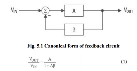
canonical form of a feedback system is shown in Figure 5 . 1, and Equation 1
describes the performance of any feedback system (an amplifier with passive
feedback Components constitute a feedback system).
Oscillation
results from an unstable state; i.e., the feedback system can’t find a stable
state because its transfer function can’t be satisfied. Equation 1 becomes
unstable when (1+Aβ) = 0 because A/0 is an undefined state. Thus, the key to
designing an oscillator is to insure that Aβ = –1 (called the Barkhausen
criterion), or using complex math the equivalent expression is Aβ = 1 –180°.
The 180° phase shift criterion applies to negative feedback systems, and 0°
phase shift applies to positive feedback systems.
The
output voltage of a feedback system heads for infinite voltage when Aβ = –1.
When the output voltage approaches either power rail, the active devices in the
amplifiers change gain, causing the value of A to change so the value of Aβ ≠1;
thus, the charge to infinite voltage slows down and eventually halts. At this
point one of three things can occur.
First,
nonlinearity in saturation or cutoff can cause the system to become stable and
lock
up.
Second,
the initial charge can cause the system to saturate (or cut off) and stay that
way for a long time before it becomes linear and heads for the opposite power
rail.
Third,
the system stays linear and reverses direction, heading for the opposite power
rail. Alternative two produces highly distorted oscillations (usually quasi
square waves), and the resulting oscillators are called relaxation oscillators.
Alternative three produces sine wave oscillators.
Phase Shift in Oscillators:
The
180° phase shift in the equation Aβ = 1 –180°
is introduced by active and passive components. The phase shift contributed
by active components is minimized
because it varies with temperature, has a wide initial tolerance, and is device
dependent.
Amplifiers
are selected such that they contribute little or no phase shift at the oscillation frequency. A single pole RL
or RC circuit contributes up to 90° phase shift per pole, and because 180° is required for oscillation,
at least two poles must be used in oscillator design.
An
LC circuit has two poles; thus, it contributes up to 180° phase shift per pole
pair, but LC and LR oscillators are not considered here because low frequency
inductors are expensive, heavy, bulky, and non-ideal. LC oscillators are
designed in high frequency applications beyond the frequency range of voltage
feedback op amps, where the inductor size, weight, and cost are less
significant.
Multiple
RC sections are used in low-frequency oscillator design in lieu of inductors.
Phase shift determines the oscillation frequency because the circuit oscillates
at the frequency that accumulates –180° phase shift. The rate of change of
phase with frequency, dS/dt, determines frequencystability.
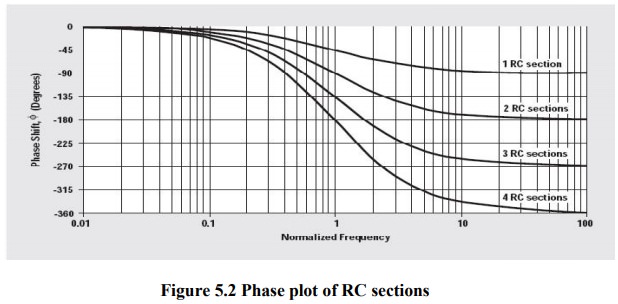
When
buffered RC sections (an op amp buffer provides high input and low output
impedance) are cascaded, the phase shift multiplies by the number of sections,
n (see Figure 2).
Although
two cascaded RC sections provide 180° phase shift, dS/dt at the oscillator
frequency is low, thus oscillators made with two cascaded RC sections have poor
frequency stability. Three equal cascaded RC filter sections have a higher
dS/dt, and the resulting oscillator has improved frequency stability.
Adding
a fourth RC section produces an oscillator with an excellent dS/dt, thus this
is the most stable oscillator configuration. Four sections are the maximum
number used
because
op amps come in quad packages, and the four-section oscillator yields four sine
waves that are 45° phase shifted relative to each other, so this oscillator can
be used to obtain sine/cosine or quadrature sine waves.
Applications
Crystal
or ceramic resonators make the most stable oscillators because resonators have
an extremely high dS/dt resulting from their non-linear properties.
Resonators
are used for high- frequency oscillators, but low-frequency oscillators do not use
resonators because of size, weight, and cost restrictions.
Op
amps are not used with crystal or ceramic resonator oscillators because op amps
have low bandwidth. It is more cost-effective to build a high- frequency
crystal oscillator and count down the output to obtain a low frequency than it
is to use a low-frequency resonator.
Gain in Oscillators:
The
oscillator gain must equal one (Aβ = 1–180°) at the oscillation frequency. The
circuit becomes stable when the gain exceeds one and oscillations cease. When
the gain exceeds one with a phase shift of –180°, the active device
non-linearity reduces the gain to one.
The
non-linearity happens when the amplifier swings close to either power rail
because cutoff or saturation reduces the active device (transistor) gain. The
paradox is that worst-case design practice requires nominal gains exceeding one
for manufacturability, but excess gain causes more distortion of the output
sine wave.
When
the gain is too low, oscillations cease under worst-case conditions, and when
the gain is too high, the output wave form looks more like a square wave than a
sine wave.
Distortion
is a direct result of excess gain overdriving the amplifier; thus, gain must be
carefully controlled in low distortion oscillators.
Phase-shift
oscillators have distortion, but they achieve low-distortion output voltages
because cascaded RC sections act as distortion filters. Also, buffered
phase-shift oscillators have low distortion because the gain is controlled and
distributed among the buffers.
Related Topics