Chapter: Electronic Circuits : Oscillators
Wien Bridge Oscillator
WIEN BRIDGE OSCILLATOR
One of the simplest sine wave oscillators which
uses a RC network in place of the conventional LC tuned tank circuit to produce
a sinusoidal output waveform, is the Wien Bridge Oscillator.
The Wien Bridge Oscillator is so called because
the circuit is based on a frequency-selective form of the Whetstone bridge
circuit. The Wien Bridge oscillator is a two-stage RC coupled amplifier circuit
that has good stability at its resonant frequency, low distortion and is very
easy to tune making it a popular circuit as an audio frequency oscillator
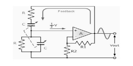
Wien Bridge Oscillator

The output of the operational amplifier is fed
back to both the inputs of the amplifier. One part of the feedback signal is
connected to the inverting input terminal (negative feedback) via the resistor
divider network of R1 and R2 which allows the amplifiers voltage gain to be
adjusted within narrow limits.
The other part is fed back to the non-inverting
input terminal (positive feedback) via the RC Wien Bridge network. The RC
network is connected in the positive feedback path of the amplifier and has
zero phase shift a just one frequency. Then at the selected resonant frequency,
( ƒr ) the voltages applied to the inverting and non-inverting inputs will be
equal and "in-phase" so the positive feedback will cancel out the
negative feedback signal causing the circuit to oscillate.
Also the voltage gain of the amplifier circuit
MUST be equal to three "Gain =3" for oscillations to start. This
value is set by the feedback resistor network, R1 and R2 for an inverting
amplifier and is given as the ratio -R1/R2.
Also, due to the open-loop gain limitations of
operational amplifiers, frequencies above 1MHz are unachievable without the use
of special high frequency op-amps. Then for oscillations to occur in a Wien
Bridge Oscillator circuit the following conditions must apply.
1. With no input signal the Wien Bridge
Oscillator produces output oscillations.
2. The Wien Bridge Oscillator can produce a
large range of frequencies.
3. The Voltage gain of the amplifier must be at
least 3.
4. The network can be used with a Non-inverting
amplifier.
5. The input resistance of the amplifier must
be high compared to R so that the RC network is not overloaded and alter the
required conditions.
6.
The output resistance of the amplifier must be low so that the effect of
external loading is minimised.
7. Some method of stabilizing the amplitude of the
oscillations must be provided because if the voltage gain of the amplifier is too small the desired oscillation
will decay and stop and if it is too large the output amplitude rises to the
value of the supply rails, which saturates the op-amp and causes the output
waveform to become distorted.
8.
With amplitude stabilisation in the form of feedback diodes, oscillations from
the oscillator can go on indefinitely.
Related Topics