Chapter: Electronic Circuits : Oscillators
Basic Transistor LC Oscillator Circuit
Basic
Transistor LC Oscillator Circuit

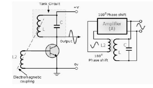
A Bipolar Transistor is used as the LC
oscillators amplifier with the tuned LC tank circuit acts as the collector
load. Another coil L2 is connected between the base and the emitter of the
transistor whose electromagnetic field is "mutually" coupled with
that of coil L. Mutual inductance exists between the two circuits.
The changing current flowing in one coil
circuit induces, by electromagnetic induction, a potential voltage in the other
(transformer effect) so as the oscillations occur in the tuned circuit,
electromagnetic energy is transferred from coil L to coil L2 and a voltage of
the same frequency as that in the tuned circuit is applied between the base and
emitter of the transistor.
In this way the necessary automatic feedback voltage is applied to
the amplifying transistor. The amount of feedback can be increased or decreased
by altering the coupling between the two coils L and L2. When the circuit is
oscillating its impedance is resistive and the collector and base voltages are
180 out of phase. In order to maintain oscillations (called frequency
stability) the voltage applied to the tuned circuit must be
"in-phase" with the oscillations occurring in the tuned circuit.
Therefore, we must introduce an additional 180o
phase shift into the feedback path between the collector and the base. This is
achieved by winding the coil of L2 in the correct direction relative to coil L
giving us the correct amplitude and phase relationships for the
Oscillatorscircuit or by connecting a phase shift network between the output
and input of the amplifier.
The LC Oscillator is therefore a
"Sinusoidal Oscillator" or a "Harmonic Oscillator" as it is
more commonly called. LC oscillators can generate high frequency sine waves for
use in radio frequency (RF) type applications with the transistor amplifier
being of a Bipolar Transistor or FET.
Harmonic Oscillators come in many different
forms because there are many different ways to construct an LC filter network
and amplifier with the most common being the Hartley LC Oscillator, Colpitts LC Oscillator, Armstrong Oscillator and Clapp
Oscillator to name a few.
Related Topics