Chapter: Electronic Circuits : Oscillators
RC Phase-Shift Oscillator
RC Phase-Shift Oscillator
In a RC Oscillator the input is shifted 180o through the amplifier stage and180o again through a second inverting stage giving us "180o + 180o = 360o" of phase shift which is the same as 0o thereby giving us the required positive feedback. In other words, the phase shift of the feedback loop should be "0".
In a Resistance-Capacitance Oscillator or
simply an RC Oscillator, we make use of the fact that a phase shift occurs
between the input to a RC network and the output from the same network by using
RC elements in the feedback branch, for example.
RC Phase-Shift Network
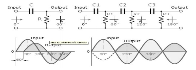
The circuit on the left shows a single resistor
-capacitor network and whose output voltage "leads" the input voltage
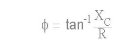
by some angle less than 90 o. An ideal RC circuit would produce a phase shift of
exactly 90o.The amount of actual phase shift in the circuit depends upon the
values of the resistor and the capacitor, and the chosen frequency of oscillati
ons with the phase angle ( Φ ) being given as:
RC Oscillator Circuit
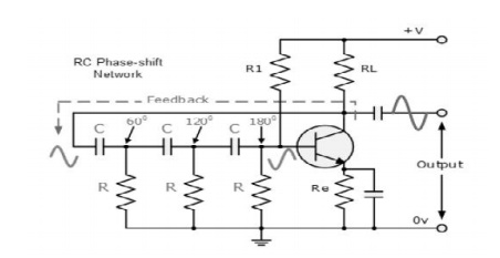
The RC Oscillator which is also called a Phase
Shift Oscillator, produces a sine
wave output signal using regenerative feedback from the resistor- capacitor
combination. This regenerative feedback from the RC network is due to the
ability of the capacitor to store an electric charge, (similar to the LC tank
circuit).
This resistor-capacitor feedback network can be
connected as shown above to produce a leading phase shift (phase advance
network) or interchanged to produce a lagging phase shift (phase retard
network) the outcome is still the same as the sine wave oscillations only occur
at the frequency at which the overall phase-shift is 360o. By
varying one or more of the resistors or capacitors in the phase-shift network,
the frequency can be varied and generally this is done using a 3-ganged
variable capacitor
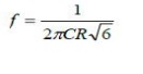
If all the resistors, R and the capacitors, C
in the phase shift network are equal in value, then the frequency of
oscillations produced by the RC oscillator is given as:
Op-amp RC Oscillator Circuit
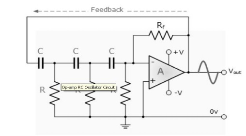
As the feedback is connected to the
non-inverting input, the operational amplifier is therefore connected in its
"inverting amplifier" configuration which produces the required 180o
phase shift while the RC network produces the other 180o phase shift
at the required frequency (180o + 180o).
Although it is possible to cascade together
only two RC stages to provide the required 180o of phase shift (90o
+ 90o), the stability of the oscillator at low frequencies is poor.
One of the most important features of an RC Oscillator is its frequency stability which is its ability too provide a constant frequency output under varying load conditions. By cascading three or even four RC stages together (4 x 45o), the stability of the oscillator can be greatly improved.
RC Oscillators with four stages are generally
used because commonly available operational amplifiers come in quad IC packages
so designing a 4- stage oscillator with 45o of phase shift relative
to each other is relatively easy.
Related Topics