Chapter: Electronic Circuits : Oscillators
Basic Oscillator Feedback Circuit
Basic
Oscillator Feedback Circuit
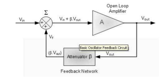
Where: β is a feedback fraction.
1. Without Feedback
2. With Feedback
Oscillators are circuits that generate a
continuous voltage output waveform at a required frequency with the values of
the inductors, capacitors or resistors forming a frequency selective LC
resonant tank circuit and feedback network.
This feedback network is an attenuation network which has a gain of less than
one (β<1) and starts oscillations when A β>1 which returns to unity (A
β=1) once
oscillations commence. The LC oscillators
frequency is controlled using a tuned or resonant inductive/capacitive (LC)
circuit with the resulting output frequency being known as the Oscillation
Frequency.
By making the oscillators feedback a reactive
network the phase angle of the feedback will vary as a function of frequency
and this is called Phase-shift.
There are basically types of Oscillators:\
1.Sinusoidal Oscillators - these are known as
Harmonic Oscillators and are generally a :LC Tuned-feedback” or “RC tuned-feedback”
type Oscillator that generates a purely sinusoidal waveform which is
of constant amplitude and frequency.
2.Non-Sinusoidal Oscillators – these are known
as Relaxation Oscillators and generate complex non-sinusoidal waveforms that
changes very quickly from one condition of stability to another such as
“Square-wave”, “Triangular-wave” or
“Sawtoothed-wave” type waveforms.
3. Resonance
When a constant voltage but of varying
frequency is applied to a circuit consisting of an inductor, capacitor and
resistor the reactance of both the Capacitor/Resistor and Inductor/Resistor
circuits is to change both the amplitude and the phase of the output signal due
to the reactance of the components used.
At high frequencies the reactance of a
capacitor is very low acting as a short circuit while the reactance of the
inductor is high acting as an open circuit. At low frequencies the reverse is
true, the reactance of the capacitor acts as an open circuit and the reactance
of the inductor acts as a short circuit.
Between these two extremes the combination of
the inductor and capacitor produces a “Tuned” or “Resonant” circuit that has a
Resonant Frequency, (fr) in which the capacitive and inductive reactance’s are
equal and cancel out each other, leaving only the resistance of the circuit to
oppose the flow of current. This means that there is no phase shift as the
current is in phase with the voltage. Consider the circuit below.
Related Topics