Chapter: Mechanical : Kinematics of Machinery : Basics of Mechanisms
Whitworth quick return motion mechanism
Whitworth quick return motion mechanism:
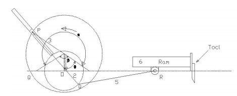
Third
inversion is obtained by fixing the crank i.e. link 2. Whitworth quick return
mechanism is an application of third inversion. This mechanism is shown in the
figure below. The crank OC is fixed and OQ rotates about O. The slider slides
in the slotted link and generates a circle of radius CP. Link 5 connects the
extension OQ provided on the opposite side of the link 1 to the ram (link 6).
The rotary motion of P is taken to the ram R which reciprocates. The quick return
motion mechanism is used in shapers and slotting machines. The angle covered
during cutting stroke from P1 to P2 in counter clockwise direction is α or 360
-2θ. During the return stroke, the angle covered is 2θ or β.
Therefore,

1. Rotary engine mechanism or
Gnome Engine:
Rotary
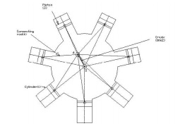
engine mechanism or gnome engine is another application of third inversion. It
is a rotary cylinder V – type internal combustion engine used as an aero –
engine. But now Gnome engine has been replaced by Gas turbines. The Gnome
engine has generally seven cylinders in one plane. The crank OA is fixed and
all the connecting rods from the pistons are connected to A. In this mechanism
when the pistons reciprocate in the cylinders, the whole assembly of cylinders,
pistons and connecting rods rotate about the axis O, where the entire
mechanical power developed, is obtained in the form of rotation of the crank
shaft. This mechanism is shown in the figure below.
2 Double
Slider Crank Chain:
A four bar
chain having two turning and two sliding pairs such that two pairs of the same
kind are adjacent is known as double slider crank chain.
3 Inversions of Double slider Crank chain:
It
consists of two sliding pairs and two turning pairs. They are three important
inversions of double slider crank chain. 1) Elliptical trammel. 2) Scotch yoke
mechanism. 3) Oldham’s Coupling.
4. Elliptical Trammel:
This is
an instrument for drawing ellipses. Here the slotted link is fixed. The sliding
block P and Q in vertical and horizontal slots respectively. The end R
generates an ellipse with the displacement of sliders P and Q.
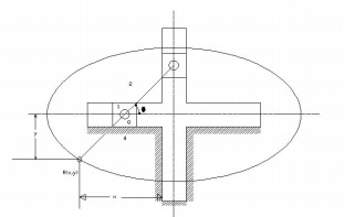
The
co-ordinates of the point R are x and y. From the fig. cos θ = x.PR
The
equation is that of an ellipse, Hence the instrument traces an ellipse. Path
traced by mid-point of PQ is a circle. In this case, PR = PQ and so

It is an
equation of circle with PR = QR = radius of a circle.
![]()
5. Scotch yoke mechanism: This
mechanism, the slider P is fixed. When PQ rotates above P, the slider Q reciprocates in the vertical
slot. The mechanism is used to convert rotary to reciprocating mechanism.
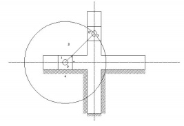
5.Oldham’s coupling: The third
inversion of obtained by fixing the link connecting the 2 blocks P & Q. If one block is turning
through an angle, the frame and the other block will also turn through the same
angle. It is shown in the figure below.
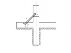
An
application of the third inversion of the double slider crank mechanism is
Oldham’s coupling shown in the figure. This coupling is used for connecting two
parallel shafts when the distance between the shafts is small. The two shafts
to be connected have flanges at their ends, secured by forging. Slots are cut
in the flanges. These flanges form 1 and 3. An intermediate disc having tongues
at right angles and opposite sides is fitted in between the flanges. The
intermediate piece forms the link 4 which slides or reciprocates in flanges 1
& 3. The link two is fixed as shown. When flange 1 turns, the intermediate
disc 4 must turn through the same angle and whatever angle 4 turns, the flange
3 must turn through the same angle. Hence 1, 4 & 3 must have the same
angular velocity at every instant. If the distance between the axis of the shaft
is x, it will be the diameter if the circle traced by the centre of the
intermediate piece. The maximum sliding speed of each tongue along its slot is
given by
v=xω
where, ω = angular velocity of each shaft in rad/sec v = linear velocity in
m/sec
Mechanical Advantage, Transmission angle:
1The
mechanical advantage (MA) is defined as the ratio of output torque to the input
torque. (or) ratio of load to output.
2 Transmission
angle.
3 The
extreme values of the transmission angle occur when the crank lies along the
line of frame.
Related Topics