Chapter: Mechanical : Kinematics of Machinery : Basics of Mechanisms
Degrees of Freedom
Degrees of Freedom:
An
unconstrained rigid body moving in space can describe the following independent
motions.
1. Translational
Motions along any three mutually perpendicular axes x, y and z,
2. Rotational
motions along these axes.
Thus a
rigid body possesses six degrees of freedom. The connection of a link with
another imposes certain constraints on their relative motion. The number of
restraints can never be zero (joint is disconnected) or six (joint becomes
solid).
Degrees
of freedom of a pair is defined as the number of independent relative motions,
both translational and rotational, a pair can have.
Degrees
of freedom = 6 – no. of restraints.
To find
the number of degrees of freedom for a plane mechanism we have an equation
known as Grubler’s equation and is given
by F = 3 ( n – 1 ) – 2 j1 – j2
F =
Mobility or number of degrees of freedom
n =
Number of links including frame.
j1 =
Joints with single (one) degree of freedom.
J2 =
Joints with two degrees of freedom.
If F >
0, results in a mechanism with ‘F’ degrees of freedom.
F = 0,
results in a statically determinate structure.
F < 0,
results in a statically indeterminate structure.
Kinematic Chain:
A
Kinematic chain is an assembly of links in which the relative motions of the
links is possible and the motion of each relative to the others is definite
(fig. a, b, and c.)
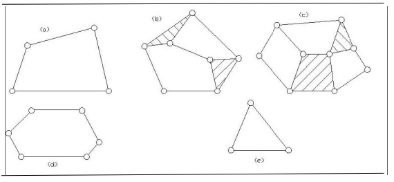
In case,
the motion of a link results in indefinite motions of other links, it is a
non-kinematic chain. However, some authors prefer to call all chains having
relative motions of the links as kinematic chains.
Linkage, Mechanism and structure:
A linkage
is obtained if one of the links of kinematic chain is fixed to the ground. If
motion of each link results in definite motion of the others, the linkage is
known as mechanism. If one of the links of a redundant chain is fixed, it is
known as a structure.
To obtain
constrained or definite motions of some of the links of a linkage, it is
necessary to know how many inputs are needed. In some mechanisms, only one
input is necessary that determines the motion of other links and are said to
have one degree of freedom. In other mechanisms, two inputs may be necessary to
get a constrained motion of the other links and are said to have two degrees of
freedom and so on.
The
degree of freedom of a structure is zero or less. A structure with negative
degrees of freedom is known as a Superstructure.
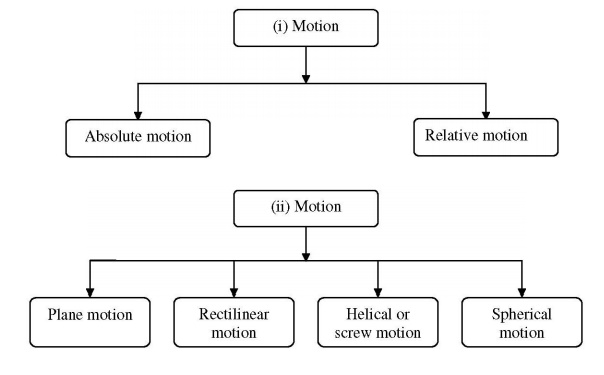
Motion and its types:
·
The three
main types of constrained motion in kinematic pairare,
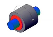
1.Completely constrained motion :
If the motion between a pair of links is limited to a definite direction, then
it is completely constrained motion. E.g.: Motion of a shaft or rod with
collars at each end in a hole as shown in fig.
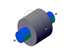
2. Incompletely Constrained motion : If the
motion between a pair of links is not confined to a definite direction, then it is incompletely constrained motion.
E.g.: A spherical ball or circular shaft in a circular hole may either rotate
or slide in the hole as shown in fig.
3. Successfully constrained
motion or Partially constrained motion: If the
motion in a definite direction is
not brought about by itself but by some other means, then it is known as
successfully constrained motion. E.g.: Foot step Bearing
·
Machine:
It is a
combination of resistant bodies with successfully constrained motion which is
used to transmit or transform motion to do some useful work. E.g.: Lathe,
Shaper, Steam Engine, etc.
·
Kinematic chain with three lower pairs
It is
impossible to have a kinematic chain consisting of three turning pairs only.
But it is possible to have a chain which consists of three sliding pairs or
which consists of a turning, sliding and a screw pair.
The
figure shows a kinematic chain with three sliding pairs. It consists of a frame
B, wedge C and a sliding rod A. So the three sliding pairs are, one between the
wedge C and the frame B, second between wedge C and sliding rod A and the frame
B.
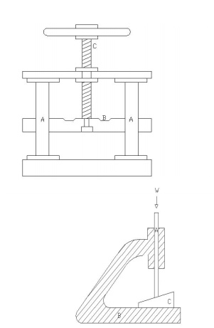
This
figure shows the mechanism of a fly press. The element B forms a sliding with A
and turning pair with screw rod C which in turn forms a screw pair with A. When
link A is fixed, the required fly press mechanism is obtained.
Related Topics