Chapter: Mechanical : Kinematics of Machinery : Basics of Mechanisms
Kinematic Inversions of 4-bar chain and slider crank chains
Kinematic Inversions of 4-bar
chain and slider crank chains:
·
Types of Kinematic Chain: 1) Four bar
chain 2) Single slider chain 3) Double Slider chain
·
Four bar
Chain:
The chain
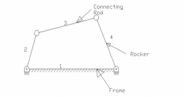
has four links and it looks like a cycle frame and hence it is also called quadric cycle chain. It is shown in the
figure. In this type of chain all four pairs will be turning pairs.
·
Inversions:
By fixing
each link at a time we get as many mechanisms as the number of links, then each
mechanism is called ‘Inversion’ of the original Kinematic Chain.
Inversions of four bar chain mechanism:
There are
three inversions: 1) Beam Engine or Crank and lever mechanism. 2) Coupling rod
of locomotive or double crank mechanism. 3) Watt’s straight line mechanism or
double lever mechanism.
·
Beam
Engine:
When the
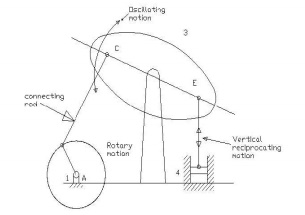
crank AB rotates about A, the link CE pivoted at D makes vertical reciprocating
motion at end E. This is used to convert rotary motion to reciprocating motion
and vice versa. It is also known as Crank and lever mechanism. This mechanism
is shown in the figure below.
2. Coupling rod of locomotive: In this mechanism the length of
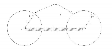
link AD = length of link C. Also length
of link AB = length of link CD. When AB rotates about A, the crank DC rotates
about D. this mechanism is used for coupling locomotive wheels. Since links AB
and CD work as cranks, this mechanism is also known as double crank mechanism.
This is shown in the figure below.
3. Watt’s straight line mechanism or Double
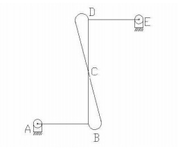
lever mechanism: In this mechanism, the links AB & DE act as levers
at the ends A & E of these levers are fixed. The AB & DE are parallel
in the mean position of the mechanism and coupling rod BD is perpendicular to
the levers AB & DE. On any small displacement of the mechanism the tracing
point ‘C’ traces the shape of number ‘8’, a portion of which will be
approximately straight. Hence this is also an example for the approximate
straight line mechanism. This mechanism is shown below.
·
2. Slider
crank Chain:
It is a
four bar chain having one sliding pair and three turning pairs. It is shown in
the figure below the purpose of this mechanism is to convert rotary motion to
reciprocating motion and vice versa. Inversions of a Slider crank chain:
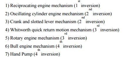
There are four inversions in a single slider chain
mechanism. They are:
·
1.
Reciprocating engine mechanism :
In the
first inversion, the link 1 i.e., the cylinder and the frame is kept fixed. The
fig below shows a reciprocating engine.
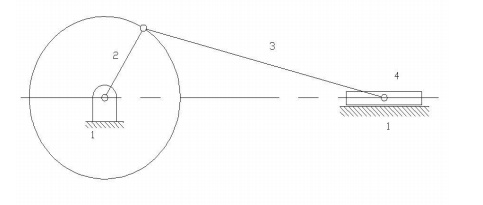
A slotted
link 1 is fixed. When the crank 2 rotates about O, the sliding piston 4
reciprocates in the slotted link 1. This mechanism is used in steam engine,
pumps, compressors, I.C. engines, etc.
·
2. Crank
and slotted lever mechanism:
It is an
application of second inversion. The crank and slotted lever mechanism is shown
in figure below.
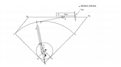
In this
mechanism link 3 is fixed. The slider (link 1) reciprocates in oscillating
slotted lever (link 4) and crank (link 2) rotates. Link 5 connects link 4 to
the ram (link 6). The ram with the cutting tool reciprocates perpendicular to
the fixed link 3. The ram with the tool reverses its direction of motion when
link 2 is perpendicular to link 4. Thus the cutting stroke is executed during
the rotation of the crank through angle α and the return stroke is executed
when the crank rotates through angle β or 360 – α. Therefore, when the crank
rotates uniformly, we get

This
mechanism is used in shaping machines, slotting machines and in rotary engines.
Related Topics