Chapter: Civil : Railway Airport Harbour Engineering : Railway Engineering : Track and Track Stresses
Vertical Loads on Railway
Vertical Loads
Dead load of vehicles at rail-wheel contact
The value of dead load is usually taken from the axle-load diagram. It is, however, brought out that for various reasons the actual wheel loads, even in the static state on a level and perfect track, may be different from the nominal values. Cases have sometimes come to notice where a steam locomotive had a higher axle load than the nominal load or had different right and left wheel loads.
Dynamic augment of vertical loads
On account of vertical impact due to speed and rail vibrations, etc., the dynamic load is much more than the static load. The dynamic wheel load is obtained by increasing the static wheel load by an incremental amount given by the speed factor. Till 1965 Indian Railways used the 'Indian Formula' for calculating the speed factor. This formula is the following:
where V is the speed in km/h.
At a speed of 60 mph, the Indian formula gives a speed factor of 55%, whereas the German formula, as used by RDSO, gives a speed factor of 30%. Investigations have been carried out by RDSO and different values of speed factors have been recommended for different types of vehicles running at different speeds.
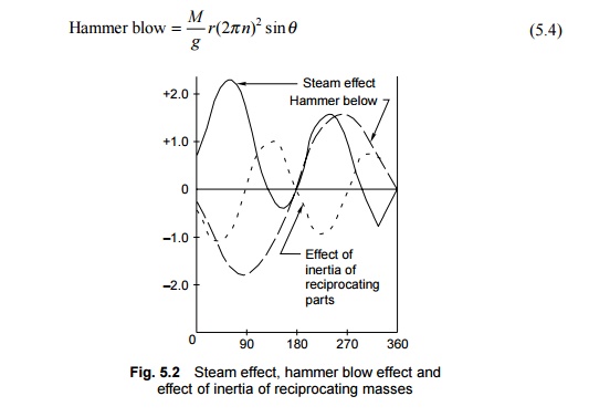
Hammer blow effect
The centrifugal forces due to revolving masses in the driving and coupled wheels of a locomotive, such as crank pins, coupling rods, and parts of the connecting rod, are completely balanced by placing counterweights near the rim of the wheel, diametrically opposite to the revolving masses. The reciprocating masses of the piston, piston rod, cross head, and part of the connecting rod, by virtue of their inertia and oscillatory movement, produce alternating forces in the direction of the stroke and tend to cause the locomotive to oscillate sideways and nose across the track. In order to reduce this nosing tendency, a weight is introduced onto the wheels at the opposite side of the crank. The horizontal component of the centrifugal force of this added weight balances the inertial force in the line of stroke, but the vertical component throws the wheel out of balance in the plane perpendicular to the line of stroke. The vertical component of the centrifugal force of the weight introduced to balance the reciprocating masses causes variation in the wheel pressure on the rail, and is called the hammer blow. The heavier the weight added to balance the reciprocating masses, the greater the hammer blow.
The hammer blow effect occurs only in the case of steam locomotives. The hammer blow can be calculated as follows (Fig. 5.2):
where M is the net overweight in lbs, r is the crank pin diametre in ft, n is the number of revolutions of the wheel per second, and ? is the crank angle.
Steam effect
A steam locomotive works by converting coal energy into steam energy. Steam pressure acts on the piston and is transmitted to the driving wheels through the crank pins and connecting rod. The vertical component of the crank pins and connecting rod is at an angle to the piston rod. Its value is given by the formula
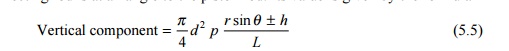
where L is the length of the connecting rod in inches, h is the height of the cross head above the centre line of the driving wheel in inches, and ? is the crank angle, i.e., the angle traversed by the crank since the beginning of the stroke.
The steam effect (Fig. 5.2) does not scynchronize with the hammer blow effect due to overbalance and is additional to the hammer blow only during some part of the revolution of the crank shaft.
Inertia of reciprocating masses
The reciprocating masses, due to their inertia and acceleration, alter the forces on the piston, and hence the force in the connecting rod is also affected during the revolution of the wheel.

where M is the mass of the reciprocating parts, L is the length of the connecting rod, n is the number of revolutions per second, h is the height of the cross head above the centre line of the driving wheel, and ? is the crank angle.
The maximum combined force of the hammer blow, the steam effect, and inertia for each driving wheel and the hammer blow effect of the coupled wheels do not act simultaneously due to the phase difference in the angular position of the counterweights in the coupled and driving wheels. The maximum combined effect of these forces is obtained by summing up the three curves for one complete revolution of the wheel.
Bending stresses on the rail due to vertical loads
The general theory of bending of rails is based on the assumption that the rail is a long bar continuously supported by an elastic foundation. Due to vertical loads, the rail is subjected to bending or flexural stresses. The bending stresses that a rail is subjected to as a result of vertical loads are illustrated in Fig. 5.3. The theory of stresses in rails takes into account the elastic nature of the supports. Based on this theory, the formula for bending moment is
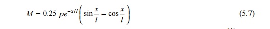
where M is the bending moment, P is the isolated vertical load, l ? (EI/?)1/ 4 is the characteristic length, EI is the flexural stiffness of the rail, ? is the track modulus, and x is the distance of the point from the load.
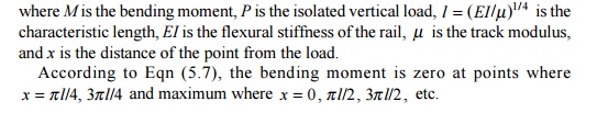
According to Eqn (5.7), the bending moment is zero at points where x ? ? l /4, 3? l/4 and maximum where x ? 0 , ? l /2, 3? l/2 , etc.
For calculating the stresses acting on the rail, first the maximum bending moment caused due to a series of loads moving on the rail is calculated as per Eqn (5.7). The bending stress is then calculated by dividing the bending moment by the sectional modulus of the rail. The permissible value of bending stress due to a vertical load and its eccentricity is 23.5 kg/mm2 for rails with a 72 UTS.
Related Topics