Chapter: Civil : Railway Airport Harbour Engineering : Railway Engineering : Track and Track Stresses
Stresses on the Railway Track
Stresses on the Track
Stresses on the track due to the various kinds of forces applied on it are discussed in the following sections.
Lateral forces
The lateral force applied to the rail head produces a lateral deflection and twist in the rail. Lateral force causes the rail to bend horizontally and the resultant torque causes a huge twist in the rail as well as the bending of the head and foot of the rail. Lateral deflection of the rail is resisted by the friction between the rail and the sleeper, the resistance offered by the rubber pad and fastenings, as well as the ballast coming in contact with the rail.
The combined effect of lateral forces resulting in the bending and twisting of a rail can be measured by strain gauges. Field trials indicate that the loading wheels of a locomotive may exert a lateral force of up to 2 t on a straight track particularly at high speeds.
Longitudinal forces
Due to the tractive effort of the locomotive and its braking force, longitudinal stresses are developed in the rail. Temperature variations, particularly in welded rails, result in thermal forces, which also lead to the development of stresses. The exact magnitude of longitudinal forces depends on many variable factors. However, a rough idea of these values is as follows:
(a) Longitudinal forces on account of 30-40% weight of locomotive of tractive effort for alternating current (ac).
(b) Longitudinal forces on account of 15-20% of weight of braking force of the
locomotive and 10-15% weight of trailing load.
Tensile stresses are induced in winter due to contraction and compressive stresses are developed in summer due to compression. The extreme value of these stresses can be 10.75 kg/mm2 in winter and 9.5 kg/mm2 in summer.
Contact stresses between rail and wheel
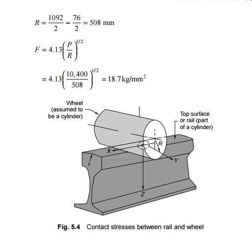
Hertz formulated a theory to determine the area of contact and the pressure distribution at the surface of contact between the rail and the wheel. As per this theory, the rail and wheel contact is similar to that of two cylinders (the circular wheel and the curved head of the rail) with their axes at right angles to each other. The area of contact between the two surfaces is bound by an ellipse as shown in Fig. 5.4.
The maximum contact shear stress (F) at the contact point between the wheel and the rail is given by the empirical formula
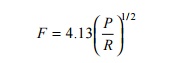
where F is the maximum shear stress in kg/mm2, R is the radius of the fully worn out wheel in mm, and P is the static wheel load in kg + 1000 kg for on-loading on curves
Contact stress for the WDM2 locomotive Static wheel load (P) = 9400 + 1000 = 10,400 kg. Radius of worn out wheel for maximum wear of 76 mm (38 mm radius reduction):
The contact stress for the WDM2 locomotive as such is 18.7 kg/mm2. The maximum value is, however, limited to 21.6 kg/mm2, which is 30% of the UTS value (72 kg/mm2) of the rail.
Surface defects
A flat on the wheel or a low spot on the rail causes extra stresses on the rail section. Empirical studies reveal that an additional deflection of about 1.5 times the depth of the flat or low spot occurs at the critical speed (about 30 km/h). Additional bending moment is caused on this account with a value of about 370,000 kg cm for the BG group A route with the WDM4 locomotive.
Stresses on a sleeper
The sleepers are subjected to a large number of forces such as dead and live loads, dynamic components of tracks such as rails and sleeper fastenings, maintenance standards, and other such allied factors. Based on the elastic theory, the maximum load on a rail seat is given by the following formula:
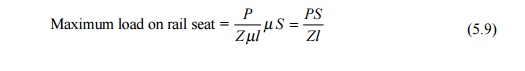
where P is the wheel load, � is the track modulus, S is the sleeper spacing, l is the characteristic length, and Z is the modulus of the rail section.
The maximum load on the rail seat is 30%-50% of the dynamic wheel load, depending on various factors and particularly the packing under the sleeper.
The distribution of load under the sleeper is not easy to determine. The pattern of distribution depends on the sleeper as well as on the firmness of the packing under the sleeper. As the ballast yields under the load, the pressure under the sleeper is not uniform and varies depending on the standard of maintenance. The following two extreme conditions may arise.
End-bound sleeper The newly compacted ballast is well compacted under the sleeper and the ends of the sleepers are somewhat hard packed. The deflection of the sleeper at the centre is more than that at the ends.
Centre-bound sleeper As trains pass on the track, the packing under the sleeper tends to become loose because of the hammering action of the moving loads. The sleeper thus tends to be loose under the rail seat. Alternatively, due to defective packing, the sleeper is sometimes hard packed at the centre.
Stresses on ballast
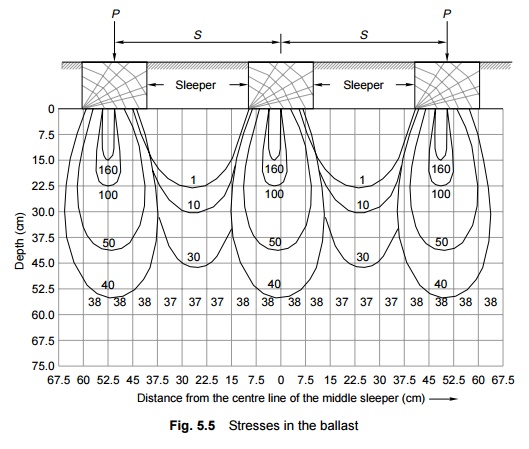
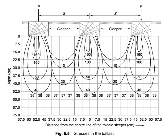
The load passed onto the sleeper from the rail is in turn transferred to the ballast. The efficacy of this load transmission depends not only on the elasticity of the sleeper but also on the size, shape, and depth of the ballast as well as the degree of compaction under the sleeper. Professor A.N. Talbot has analysed the pressure distribution in the ballast under the sleeper and investigations reveal that the pressure distribution curve under the sleeper would be shaped like bulbs as shown in Fig. 5.5.
The following are the important conclusions drawn from Fig. 5.5.
(a) The pressure on the sleeper is maximum at the centre of its width. This pressure decreases from the centre towards the ends.
(b) The vertical pressure under the sleeper is uniform at a depth approximately equal to the spacing between the sleepers.
Pressure on formation or subgrade
The live as well as dead loads exerted by the trains and the superstructure are finally carried by the subgrade. The pressure on the subgrade depends not only on the total quantum of the load but also on the manner in which it is transferred to the subgrade. The spacing between the sleepers; the size, depth, as well as compaction of the ballast under the sleeper; and the type of subgrade play an important role in the distribution of pressure on the subgrade.
The values of maximum formation pressure permitted on Indian Railways are the following:
For motive power
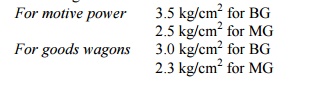
For goods wagons
Relief of stresses
A train load consists of a number of wheel loads close to each other which act simultaneously on the rail. A single isolated wheel load creates much more bending moment in the rail as compared to a group of wheel loads, which on account of the negative bending moment under adjacent wheels provide what known as a 'relief of stresses'. The rail stresses in this case are comparatively smaller. The value of relief of stresses depends upon the distance of the point of contraflexure of the rail and the spacing between the wheels, but its value can be as high as 50%.
Permissible stresses on a rail section
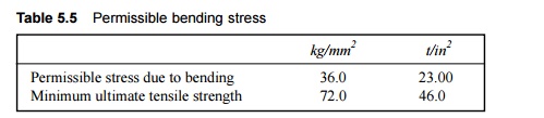
The permissible bending stresses due to vertical load and its eccentricity, and lateral load on a rail section on Indian Railways is given in Table 5.5.
Table 5.5 Permissible bending stress
The stresses on a rail are measured by any of the following methods depending upon the facilities available.
(a) Photo-elastic method
(b) Electric resistance strain gauge method
(c) Method employed using special test frame
At present, Indian Railways mostly uses the electric resistance strain gauges for measuring rail stresses.
Whenever a new locomotive or rolling stock design is introduced on the Railways, a detailed study is carried out followed by field trials to ensure that the permitted speed of the new locomotive or rolling stock does not cause excessive stresses on the track. The same stipulations are made whenever there is an increase in the speed or axle load of the existing locomotive or rolling stock design.
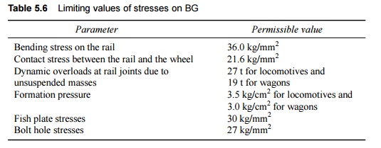
The various parameters and their limiting values required to be checked for BG are given in Table 5.6.
Table 5.6 Limiting values of stresses on BG
Related Topics