Chapter: Mechanical : Metrology and Measurements : Laser Metrology
Use of Laser
Use of Laser
· Laser Telemetric
system
Laser telemetric system is a non-contact
gauge that measures with a collimated laser beam. It measures at the rate of
150 scans per second. It basically consists of three components, a transmitter,
a receiver and processor electronics. The transmitter module produces a
collimated parallel scanning laser beam moving at a high constant, linear
speed. The scanning beam appears a red line. The receiver module collects and
photoelically senses the laser light transmitted past the object being
measured. The processor electronics takes the received signals to convert them
10 a convenient form and displays the dimension being gauged. The transmitter
contains a low power helium-neon gas laser and its power supply, a specially
designed collimating lens, a synchronous motor, a multi faceted reflector
prism, a synchronous pulse photo detector and a protective replaceable window.
The high speed of scanning permits on line gauging and thus it is possible to
detect changes in dimensions when components are moving on a continuous product
such as in rolling process moving at very high speed. There is no need of
waiting or product to cool for taking measurements. This system can also be
applied on production machines and control then with closed feedback loops.
Since the output of this system is available in digital form, it can run a
process controller limit alarms can be provided and output can be taken on
digital printer.
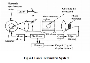
Fig
4.1 Laser Telemetric System
· Laser and LED based distance measuring instruments
These can measure distances from I to
2in with accuracy of the order of 0. 1 to 1% of the measuring range When the
light emitted by laser or LED hits an object, scatter and some of this
scattered light is seen by a position sensitive detector or diode array. If the
distance between the measuring head and the object changes. The angle at which
the light enters the detector will also change. The angle of deviation is
calibrated in terms of distance and output is provided as 0-2OmA. Such
instruments are very reliable because there are no moving parts their response
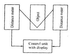
time is milliseconds. The measuring system uses two distance meters placed at
equal distance on either side of the object and a control unit to measure the
thickness of an object. The distance meter is focused at the centre of the
object.
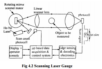
· Scanning Laser gauge
Fig shows a schematic diagram of a
scanning laser gauge. It consist of transmitter, receives and processor
electronics. A thin band of scanning laser light is made to pass
through a linear scanner lensbjectplacedtoina
parallelrender i beam, casts a time dependent shadow. Signal from the light
entering the photocell
(receiver) arc proc by a microprocessor to provide
display of the dimension represented by the time difference between the shadow
edges. It can provide results to an accuracy of0.25 for 10—50mm diameter
objects. It can be used for objects 0.05mm to 450mm diameter; and offers
repeatability of 0.1µm
· Photo diode away imaging
The
system comprises of laser source, imaging optics. Photo-diode array. Signal
processor and display unit. For large parts, two arrays in which one for each
edge are used. Accuracies as high as 0.05 µm have been achieved.
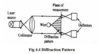
· Diffraction pattern technique
These are used to measure small gaps and
small diameter parts. A parallel coherent laser beam is diffracted by a small
part and a lens on a linear diode array focuses the resultant pattern. Its use
is restricted to small wires. The measurement accuracy is more for smaller
parts. The distance between the alternating light and dark hands in the
diffraction pattern is a (tired function of the wile diameter, wavelength of
laser beam and the focal length of the lens.
· Two- frequency laser interferometer
Fig.
shows schematic arrangement. This consists of two frequency laser head, beam
directing and splitting optics, measurement optics, receivers, and wavelength
compensators and electronics. It is ideally suited for measuring linear
positioning straightness in two planes, pitch and yaw.
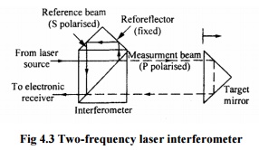
The two-frequency laser head provides
one frequency with P-polarization and another frequency with S-polarization.
The laser beam is split at the polarizing beam splitter into its two separate
frequencies. The measuring beam is directed through the interferometer to
reflect off a target mirror or retro reflector attached to the object to be
measured. The reference beam is reflected from fixed retro reflector. The
measurement beam on its return path recombines with the reference beam and is
directed to the electronic receiver.
· Gauging wide diameter from the diffraction pattern
formed in a laser
Figure
shows a method of measuring the diameter of thin wire using the interference
fringes resulting from diffraction of the light by the wire in the laser beam.
A measure of the diameter can be obtained by moving the photo detector until
the output is restored to its original value. Variation in wire diameter as
small as 0.2% over wire diameter from 0.005 to 0.2mm can be measured.
Figure
shows the length measurement by fringe counting. The laser output, which may be
incoherent illumines three slits at a time in the first plane which form
interference fringes. The movement can be determined by a detector. The total
number of slits in the first plane is governed by the length over which
measurement is required
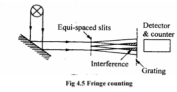
The spacing between the slits and
distance of the slit to the plane of the grating depend on the wavelength of
the light used.
Related Topics