Chapter: Mechanical : Metrology and Measurements : Laser Metrology
Computer Controlled Co-Ordinate Measuring Machine
Computer Controlled
Co-Ordinate Measuring Machine
·
The measurements, inspection of parts
for dimension form, surface characteristics and position of geometrical
elements are done at the same time.
·
Mechanical system can be divided into
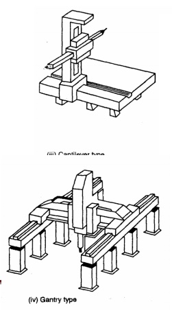
four basic types. The selection will be depends on the application.
1. Column
type.
2. Bridge
type.
3. Cantilever
type.
4. Gantry
type.
All these machines use
probes which may be trigger type or measuring type. This is connected to the
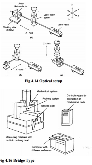
spindle in Z direction. The main features of this system are shown in figure

Fig 4.15 Column Type
Fig 4.16 Bridge Type

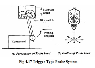
Trigger type probe
system

Fig
4.17 Trigger Type Probe System
·
The buckling mechanism is a three point
hearing the contacts which are arranged at 1200 around the circumference. These
contacts act as electrical micro switches.
·
When being touched in any probing
direction one or f contacts is lifted off and the current is broken, thus
generating a pulse, when the circuit is opened, the co-ordinate positions are
read and stored.
·
After probing the spring ensures the
perfect zero position of the three-point bearing. The probing force is
determined by the pre stressed force of the spring with this probe system data
acquisition is always dynamic and therefore the measuring time is shorter than
in static principle.
Measuring
type probe system
• It is
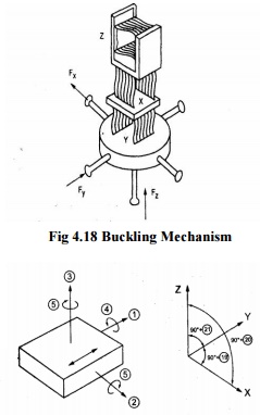
a very small co-ordinate measuring machine in which the buckling mechanism
consists of parallel guide ways when probing the spring parallelogram are
deflected from their initial position.
• Since
the entire system is free from, torsion, friction, the displacement can be
measured easily.

Fig 4.18 Buckling Mechanism
• The mathematical
model of the
mechanical system is shown in figure. If the components of the CMM are
assumed as rigid bodies, the deviations of a carriage can be described by three
displacement deviations.
• Parallel
to the axes 1, 2 and 3 and by three rotational deviations about the axes 4, 5
and 6.Similarly deviations 7-12 occur for carriage and 13-18 occur for Z
carriage and the three squareness deviations 19, 20 and 21 are to be measured
and to be treated in the mathematical model.
• Moving
the probe stylus in the Y direction the co-ordinate system L is not a straight line
but a curved one due to errors in the guide.
• If
moving on measure line L further corrections are required in X, Y and Z
coordinates due to the offsets X and Z from curve L resulting from the pitch
angle 5, the roll angle 4 and the yaw angle 6.
• Similarly
the deviations of all three carriages and the squareness errors can be taken
into account.
• The
effect of error correction can be tested by means of calibrated step gauges.
The
following test items are carried out for CMM.
(i)Measurement
accuracy
a. Axial length measuring accuracy b.Volumetric
length measuring accuracy
(ii)Axial
motion accuracy
a. Linear
displacement accuracy
b. Straightness
c. Perpendicularity
d. Pitch,
Yaw and roll.
The axial length measuring accuracy is
tested at the lowest position of the Z-axis. The lengths tested are
approximately 1/10, 1/5, 2/5, 3/5 and 4/5 of the measuring range of each axis
of CMM. Tile test is repeated five times for each measuring length and results
plotted and value of measuring accuracy is derived.
Related Topics