Chapter: Mechanical : Metrology and Measurements : Laser Metrology
Laser Interferometer
LASER INTERFEROMETER
It is possible to maintain the quality of
interference fringes over longer distance when lamp is replaced by a laser
source. Laser interferometer uses AC laser as the light source and the
measurements to be made over longer distance. Laser is a monochromatic optical
energy, which can be collimated into a directional beam AC. Laser
interferometer (ACLI) has the following advantages.
·
High repeatability
·
High accuracy
·
Long range optical path
·
Easy installations
·
Wear and tear
Schematic
arrangement of laser interferometer is shown in fig. Two-frequency zeeman laser
generates light of two slightly different frequencies with opposite circular
polarisation. These beams get split up by beam splitter B One part travels
towards B and from there to external cube corner here the displacement is to
the measured.
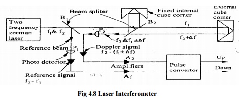
Fig 4.8 Laser Interferometer
This interferometer uses cube corner reflectors
which reflect light parallel to its angle of incidence. Beam splitter B2
optically separates the frequency J which alone is sent to the movable cube
corner reflector. The second frequency from B2 is sent to a fixed reflector
which then rejoins f1 at the beam splitter B2 to produce alternate light and
dark interference flicker at about 2 Mega cycles per second. Now if the movable
reflector moves, then the returning beam frequency Doppler-shifted slightly
up Thus the light beams moving towards photo detector P2 have
frequencies f2 and (f1 ± Δf1) and P2 changes these frequencies int signal from
beam splitter B2 and changes the reference beam frequencies f1 and f2 into
electrical signal. An AC amplifier A separates frequency. Difference signal f2
–f1 and A2 separates frequency difference signal. The pulse converter extracts
i. one cycle per half wavelength of motion. The up-down pulses are counted
electronically and displayed in analog or digital form.
Michelson
Interferometer
Michelson
interferometer consists of a monochromatic light source a beam splitter and two
mirrors. The schematic arrangement of Michelson interferometer is shown in fig.
The monochromatic light falls on a beam splitter, which splits the light into
two rays of equal intensity at right angles. One ray is transmitted to mirror
M1 and other is reflected through beam splitter to mirror M2,. From both these
mirrors, the rays are reflected back and these return at the semireflecting
surface from where they are transmitted to the eye. Mirror M2 is fixed and
mirror M1 is movable. If both the mirrors are at same distance from beam
splitter, then light will arrive in phase and observer will see bright spot due
to constructive interference. If movable mirror shifts by quarter wavelength,
then beam will return to observer 1800 out of phase and darkness will be
observed due to destructive interference
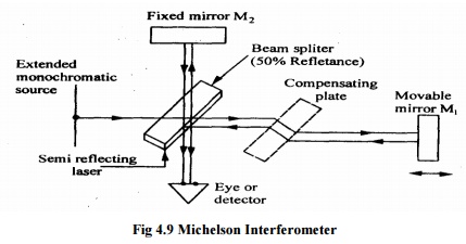
Each half-wave length of mirror travel produces a
change in the measured optical path of one wavelength and the reflected beam
from the moving mirror shifts through 360° phase change. When the reference
beam reflected from the fixed mirror and the beam reflected from the moving
mirror rejoin at the beam splitter, they alternately reinforce and cancel each
other as the mirror moves. Each cycle of intensity at the eye represents l/2 of
mirror travel. When white light source is used then a compensator plate is
introduced in each of the path of mirror M1 So that exactly the same amount of
glass is introduced in each of the path.
To
improve the Michelson interferometer
(i)
Use of laser the measurements can
be made over longer distances and highly accurate measurements when compared to
other monochromatic sources.
(ii)
Mirrors are replaced by cube-corner
reflector which reflects light parallel to its angle of incidence.
(iii)
Photocells are employed which
convert light intensity variation in voltage pulses to give the amount and
direction of position change.
Dual Frequency Laser
Interferometer
This instrument is used to measure
displacement, high-precision measurements of length, angle, speeds and
refractive indices as well as derived static and dynamic quantities. This
system can be used for both incremental displacement and angle measurements.
Due to large counting range it is possible to attain a resolution of 2mm in 10m
measuring range. Means are also provided to compensate for the influence of
ambient temperature, material temperature, atmospheric pressure and humidity
fluctuation
Twyman-Green
Interferometer
The
Twyman-Green interferometer is used as a polarizing interferometer with
variable amplitude balancing between sample and reference waves. For an exact
measurement of the test surface, the instrument error can be determined by an
absolute measurement. This error is compensated by storing the same in
microprocessor system and subtracting from the measurement of the test surface.
It
has following advantages
· It
permits testing of surface with wide varying reflectivity.
· It
avoids undesirable feedback of light reflected of the tested surface and the
instrument optics.
· It
enables utilization of the maximum available energy.
· Polarization
permits phase variation to be effected with the necessary precision.
Laser Viewers
The
profile of complex components like turbine blades can be checked by the use of
optical techniques. It is based on use of laser and CCTV. A section of the
blade, around its edge is delineated by two flat beam of laser light. This part
of the edge is viewed at a narrow angle by the TV camera or beam splitter
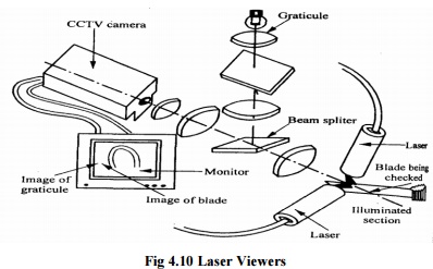
Fig
4.10 Laser Viewers
Both
blade and graticule are displayed as magnified images on the monitor, the graticule
position being adjustable so that its image can be superimposed on the profile
image. The graticule is effectively viewed at the same angle as the blade. So,
distortion due to viewing angle affects both blade and graticule. This means
that the graticule images are direct 1:1.
INTERFEROMETRIC
MEASUREMENT OF ANGLE
With
laser interferometer it is possible to measure length to accuracy of 1 part in
106 on a routine basis. With the help of two retro reflectors placed at a fixed
distance and a length measuring laser interferometer the change in angle can be
measured to an accuracy of 0.1 second. The device uses sine Principle. The line
joining the poles the retro-reflectors makes the hypotenuse of the right
triangle. The change in the path difference of the reflected beam represents
the side of the triangle opposite to the angle being measured. Such laser
interferometer can be used to measure an angle up to ± 10 degrees with a
resolution of 0. 1 second. The principle of operation is shown in fig.
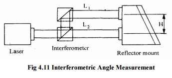
Fig
4.11 Interferometric Angle Measurement
Laser Equipment for
Alignment Testing
This testing is particularly suitable in aircraft
production, shipbuilding etc. Where a number of components, spaced long
distance apart, have to be checked to a predetermine straight line. Other uses
of laser equipment are testing of flatness of machined surfaces, checking
square ness with the help of optical square etc. These consist of laser tube
will produces a cylindrical beam of laser about 10mm diameter and an auto
reflector with a high degree of accuracy. Laser tube consists of helium-neon
plasma tube in a heat aluminum cylindrical housing. The laser beam comes out of
the housing from its centre and parallel to t stability is the order of 0.2”detectorofhead
arcand per read out unit. Number of photocell are arranged to compare laser
beam in each half horizontally and vertically. This is housed on a shard which
has two adjustments to translate the
detector in its two orthogonal measuring directions perpendicular to the laser
beam. The devices detect the alignment of flat surfaces perpendicular to a
reference line of sight.
Related Topics