Chapter: Mechanical : Metrology and Measurements : Laser Metrology
Laser Interferometry
LASER INTERFEROMETRY
Brief Description of
components
(i) Two frequency
Laser source
It is generally He-Ne type that
generates stable coherent light beam of two frequencies, one polarized
vertically and another horizontally relative to the plane of the mounting feet.
Laser oscillates at two slightly different frequencies by a cylindrical permanent
magnet around the cavity. The two components of frequencies are distinguishable
by their opposite circular polarization. Beam containing both frequencies
passes through a quarter wave and half wave plates which change the circular
polarizations to linear perpendicular polarizations, one vertical and other
horizontal. Thus the laser can be rotated by 90°about the beam axis without
affecting transducer performance. If the laser source is deviated from one of
the four optimum positions, the photo receiver will decrease. At 45° deviation
the signal will decrease to zero.
(ii) Optical elements
a)
Beam splitter
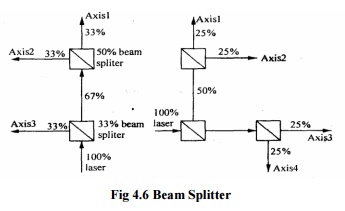
Sketch shows the beam splitters to
divide laser output along different axes. These divide the laser beam into
separate beams. To avoid attenuation it is essential that the beam splitters
must be oriented so that the reflected beam forms a right angle with the
transmitted beam. So that these two beams: are coplanar with one of the
polarisation vectors of the input form.

Fig
4.6 Beam Splitter
b)
Beam benders
These are used to deflect the light beam
around corners on its path from the laser to each axis. These are actually just
flat mirrors but having absolutely flat and very high reflectivity. Normally
these are restricted to 90° beam deflections to avoid disturbing the polarizing
vectors.
c)
Retro reflectors
These can be plane mirrors, roof prism
or cube corners. Cube corners are three mutually perpendicular plane mirrors
and the reflected beam is always parallel to the incidental beam. Each ACLI
transducers need two retro reflectors. All ACLI measurements are made by
sensing differential motion between two retro reflectors relative to an
interferometer. Plane mirror used as retro reflectors with the plane mirror
interferometer must be flat to within 0.06 micron per cm.
(iii)
Laser head’s
measurement receiver
During a measurement the laser beam is
directed through optics in the measurement path and then returned to the laser
head is measurement receiver which will detect part of the returning beam and a
doppler shifted frequency component.
(iv)
Measurement display
It contains a microcomputer to compute and display
results. The signals from receiver and measurement receiver located in the
laser head are counted in two separate pulse converter and subtracted.
Calculations are made and the computed value is displayed. Other input signals
for correction are temperature, co-efficient of expansion, air velocity etc.,
which can be displayed.
(v) Various
version of ACLI
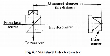
a) Standard
Interferometer
· Least
expensive.
· Retro
reflector for this instrument is a cube corner.
· Displacement
is measured between the interferometer and cube corner.

Fig
4.7 Standard Interferometer
b) Signal
beams Interferometer
· Beam
traveling between the interferometer and the retro reflector.
· Its
operation same as standard interferometer.
· The
interferometer and retro reflector for this system are smaller than the
standard system.
· Long
range optical path
· Wear
and tear.
Related Topics