Chapter: Graphics and Multimedia : Output Primitives
Two Dimensional Clipping and Viewing
TWO DIMENSIONAL GEOMETRIC TRANSFORMATIONS

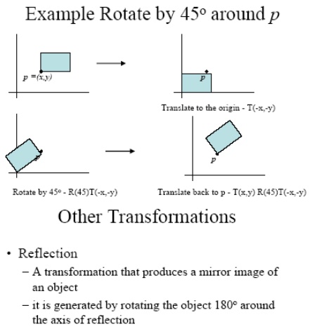
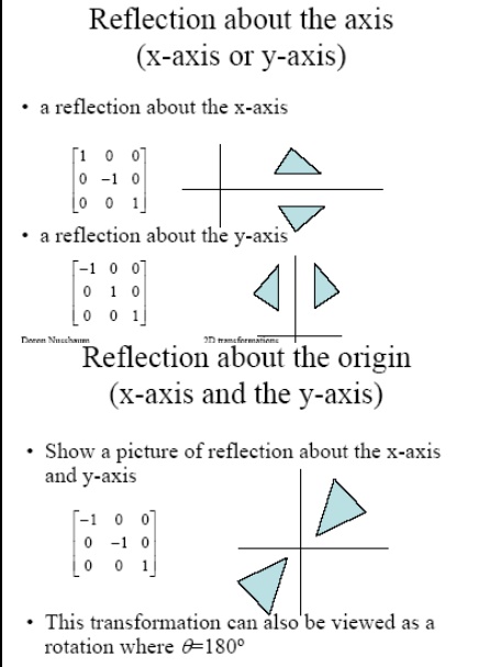
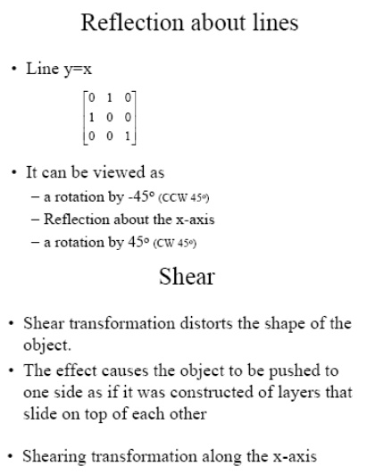
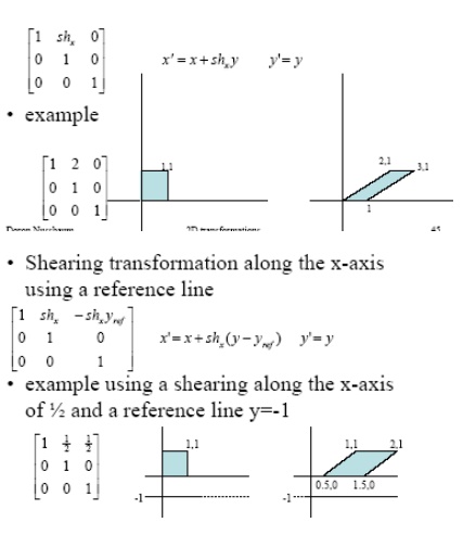
TWO DIMENSIONAL CLIPPING AND VIEWING
The Viewing Pipeline
•Window
•A world-coordinate area selected for display. defines what is to be viewed
•Viewport
•An area on a display device to which a window is mapped. defines where it is to be displayed
•Viewing transformation
•The mapping of a part of a world-coordinate scene to device coordinates.
•A window could be a rectangle to have any orientation.
Two-Dimensional Viewing
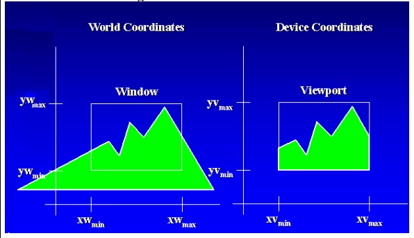
The Viewing Pipeline

Viewing Effects
•Zooming effects
Successively mapping different-sized windows on a fixed-sized viewports.
•Panning effects
Moving a fixed-sized window across the various objects in a scene.
•Device independent
Viewports are typically defined within the unit square (normalized coordinates)
Viewing Coordinate Reference FrameThe reference frame for specifying the world-coordinate window.
•Viewing-coordinate origin: P0 = (x0, y0)
•View up vector V: Define the viewing yv direction
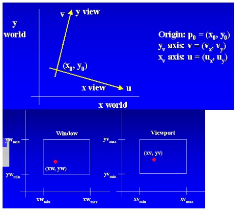
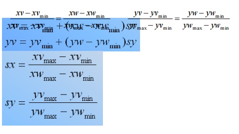
Window-to-Viewport Coordinate Transformation
Clipping Operations
• Clipping
• Identify those portions of a picture that are either inside or outside of a specified region of space.
• Clip window
• The region against which an object is to be clipped.
• The shape of clip window
• Applications of clipping
• World-coordinate clipping
Clipping Operations
• Viewport clipping
• It can reduce calculations by allowing concatenation of viewing and geometric transformation matrices.
• Types of clipping
• Point clipping
• Line clipping
• Area (Polygon) clipping
• Curve clipping
• Text clipping
• Point clipping (Rectangular clip window)
Line Clipping
Possible relationships between line positions and a standard rectangular clipping region
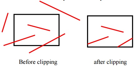
• Possible relationships
– Completely inside the clipping window
– Completely outside the window
– Partially inside the window
• Parametric representation of a line
x = x1 + u(x2 - x1) y = y1 + u(y2 - y1)
• The value of u for an intersection with a rectangle boundary edge
– Outside the range 0 to 1
– Within the range from 0 to 1
Cohen-Sutherland Line Clipping
• Region code
– A four-digit binary code assigned to every line endpoint in a picture.
– Numbering the bit positions in the region code as 1 through 4 from right to left.
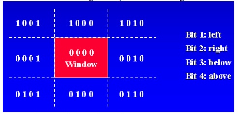
• Bit values in the region code
• Determined by comparing endpoint coordinates to the clip boundaries
• A value of 1 in any bit position: The point is in that relative position.
• Determined by the following steps:
• Calculate differences between endpoint coordinates and clipping boundaries.
• Use the resultant sign bit of each difference calculation to set the corresponding bit value.
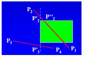
• The possible relationships:
• Completely contained within the window
• 0000 for both endpoints.
• Completely outside the window
• Logical and the region codes of both endpoints, its result is not 0000.
• Partially
Liang-Barsky Line Clipping
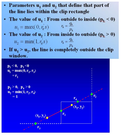
Rewrite the line parametric equation as follows:
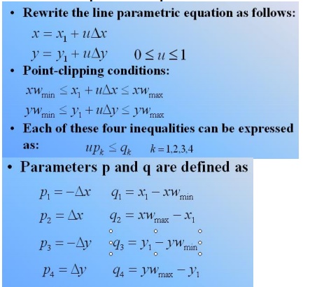
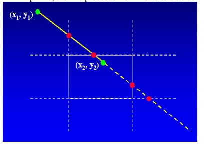
• pk = 0, parallel to one of the clipping boundary
• qk < 0, outside the boundary
• qk >= 0, inside the parallel clipping boundary
• pk < 0, the line proceeds from outside to the inside
• pk > 0, the line proceeds from inside to outside
Nicholl-Lee-Nicholl Line Clipping
• Compared to C-S and L-B algorithms
• NLN algorithm performs fewer comparisons and divisions.
• NLN can only be applied to 2D clipping.
• The NLN algorithm
• Clip a line with endpoints P1 and P2
• First determine the position of P1 for the nine possible regions.
• Only three regions need be considered
• The other regions using a symmetry transformation
• Next determine the position of P2 relative to P1.

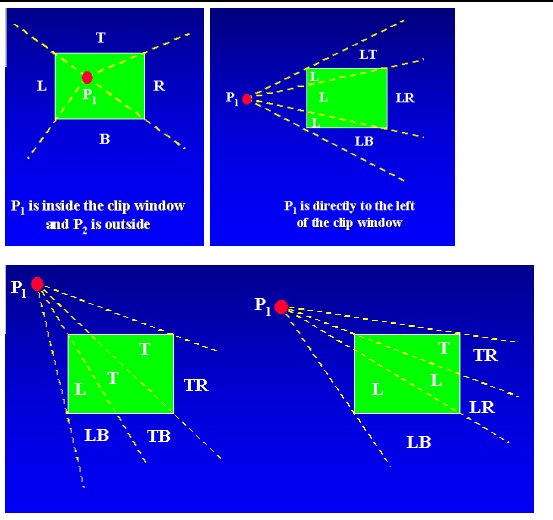
• To determine the region in which P2 is located
– Compare the slope of the line to the slopes of the boundaries of the clip region.
– Example: P1 is left of the clipping rectangle, P2 is in region LT.
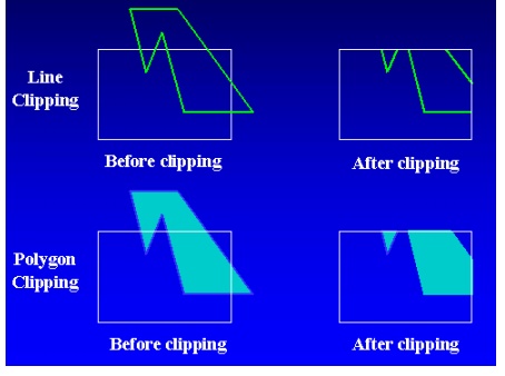
Polygon Clipping
Sutherland-Hodgeman Polygon Clipping
• Processing the polygon boundary as a whole against each window edge
• Processing all polygon vertices against each clip rectangle boundary in turn
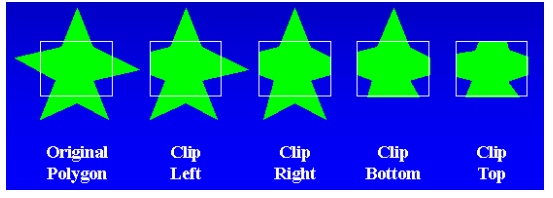
• Pass each pair of adjacent polygon vertices to a window boundary clipper
There are four cases:
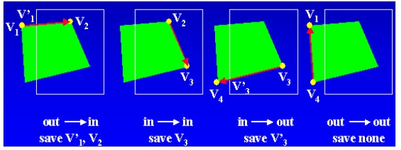
• Intermediate output vertex list
• Once all vertices have been processed for one clip window boundary, it is generated.
• The output list of vertices is clipped against the next window boundary.
• It can be eliminated by a pipeline of clipping routine.
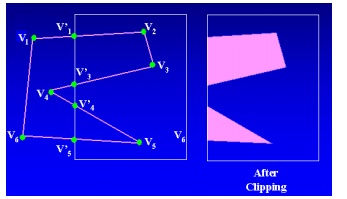
• Convex polygons are correctly clipped.
• If the clipped polygon is concave
• Split the concave polygon
Weiler-Atherton Polygon Clipping
• Developed as a method for identifying visible surfaces
• It can be applied with arbitrary polygon-clipping region.
• Not always proceeding around polygon edges
• Sometimes follows the window boundaries
• For clockwise processing of polygon vertices
• For an outside-to-inside pair of vertices, follow the polygon boundary.
• For an inside-to-outside pair of vertices, follow the window boundary in clockwise direction.
• Curve clipping
• Use bounding rectangle to test for overlap with a rectangular clip window.
• Text clipping
• All-or-none string-clipping
• All-or-none character-clipping
• Clip the components of individual characters
Related Topics