Chapter: High Voltage Engineering : Generation of High Voltages and High Currents
Tripping and Control Of Impulse Generators
TRIPPING AND CONTROL OF IMPULSE GENERATORS
In large impulse generators, the spark gaps are generally sphere gaps or gaps formed by hemispherical electrodes. The gaps are arranged such that sparking of one gap results in automatic sparking of other gaps as overvoltage is impressed on the other. In order to have consistency in sparking, irradiation from an ultra-violet lamp is provided from the bottom to all the gaps. To trip the generator at a predetermined time, the spark gaps may be mounted one movable frame, and the gap distance is reduced by moving the movable electrodes closer.
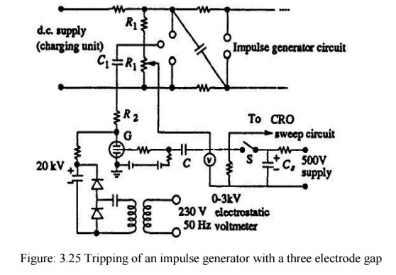
This method is difficult and does not assure consistent and controlled tripping. A simple method of controlled tripping consists of making the first gap a three electrode gap and firing it from a controlled source. Figure 3.25 gives the schematic arrangement of a three electrode gap The first stage of the impulse generator is fitted with a three electrode gap, and the central electrode is maintained at a potential in-between that of the top and the bottom electrodes with the resistors R\ and RL. The tripping is initiated by applying a pulse to the thyratron G by closing the switch S. The capacitor C produces an exponentially decaying pulse of positive polarity the pulse goes and initiates the oscillograph time base. The thyratron conducts on receiving thepulse from the switch S and produces a negative pulse through the capacitance Ci at the central electrode of the three electrode gap.
Hence, the voltage between the central electrode and the top electrode of the three electrode gap goes above its sparking potential and thus the gap conducts. The time lag required for the thyratron firing andbreakdown of the three electrode gap ensures that the sweep circuit of the oscillographbegins before the start of the impulse generator voltage. The resistance R^ ensures decoupling of voltage oscillations produced at the spark gap entering the oscilloscopethrough the common trip circuit. The three electrode gap requires larger space and an elaborate construction.Now-a-days a trigatron gap shown in Fig.3.26 is used, and this requires much smaller voltage for operation compared to the three electrode gap
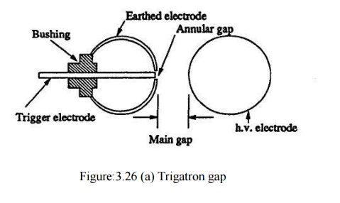
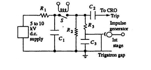
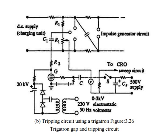
A trigatron gap consists of high voltage spherical electrode of suitable size, an earthed main electrode of spherical shape, and a trigger electrode through the main electrode. The trigger electrode is a metal rod with an annular clearance of about 1 mm fitted into the main electrode through a bushing. The trigatron is connected to a pulse circuit as shown in fig. 3.26 b. Tripping of the impulse generator is effected by a trip pulse which produces a spark between the trigger electrode and the earthed sphere. Due to space charge effects and distortion of the field in the main gap, spark over of the main gap Fig. 3.27 applied for correct operation.
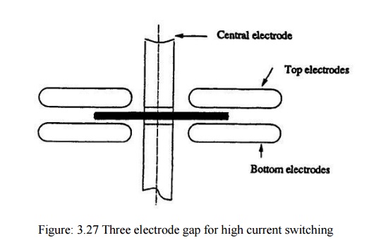
Three Electrode Gap for Impulse Current Generator
In the case of impulse current generators using three electrode gaps for tripping and control, a certain special design is needed. The electrodes have to carry high current from the capacitor bank. Secondly, the electrode has to switch large currents in a small duration of time (in about a microsecond). Therefore, the switch should have very low inductance. The erosion rate of the electrodes should be low. For high current capacitor banks, a number of spark gap switches connected in parallel as shown in Fig. 3.27 are often used to meet the requirement. Recently, trigatron gaps are being replaced by triggered vacuum gaps, the advantage of the latter being fast switching at high currents (> 100 kA) in a few nanoseconds. Triggering of the spark gaps by focused laser beams is also adopted since the performance is better than the conventional triggering methods.
Related Topics