Chapter: High Voltage Engineering : Generation of High Voltages and High Currents
Electrostatic Generator
Electrostatic Generator
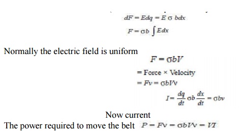
In electromagnetic generators, current carrying conductors are moved against the electromagnetic forces acting upon them. In contrast to the generator, electrostatic generators convert mechanical energy into electric energy directly. The electric charges are moved against the force of electric fields, thereby higher potential energy is gained at the cost of mechanical energy. The basic principle of operation is explained with the help of Fig. 2.7.An insulated belt is moving with uniform velocity ν in an electric field of strength E (x). Suppose the width of the belt is b and the charge density ζ consider a length dx of the belt, the charge dq = ζ bdx. The force experienced by this charge (or the force experienced by the belt).

Assuming no losses, the power output is also equal to VI.
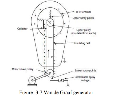
Fig. 3.8 shows belt driven electrostatic generator developed by Van de Graaf in 1931. An insulating belt is run over pulleys. The belt, the width of which may vary from a few cms to meters is driven at a speed of about 15 to 30 m/sec, by means of a motor connected to the lower pulley. The belt near the lower pully is charged electro statically by an excitation arrangement. The lower charge spray unit consists of a number of needles connected to the controllable dace. source (10 kV–100 kV) so that the discharge between the points and the belt is maintained. The charge is conveyed to the upper end where it is collected from the belt by discharging points connected to the inside of an insulated metal electrode through which the belt passes. The entire equipment is enclosed in an earthed metal tank filled with insulating gases of good dielectric strength viz. SF6 etc. So that the potential of the electrode could be raised to relatively higher voltage without corona discharges or for a certain voltage a smaller size ofthe equipment will result. Also, the shape of the h.t., electrode should be such that the surface gradient of electric field is made uniform to reduce again corona discharges, even though it is desirable to avoid corona entirely. An isolated sphere is the most favorable electrode shape and will maintain a uniform field E with a voltage of Er where r is the radius of the sphere.

As the h.t. electrode collects charges its potential rises. The potential at any instant is given as V = q/C where q is the charge collected at that instant. It appears as though if the charge were collected for a long time any amount of voltage could be generated. However, as the potential of electrode rises, the field set up by the electrode increases and that may ionize the surrounding medium and, therefore, this would be the limiting value of the voltage. In practice, equilibrium is established at a terminal voltage which is such that the charging current

equals the discharge current which will include the load current and the leakage and corona loss currents. The moving belt system also distorts the electric field and, therefore, it is placed within properly shaped field grading rings. The grading is provided by resistors and additional corona discharge elements. The collector needle system is placed near the point where the belt enters the h.t. terminal. A second point system excited by a self-inducing arrangement enables the down going belt to be charged to the polarity opposite to that of the terminal and thus the rate of charging of the latter, for a given speed, is doubled. The self inducing arrangement requires insulating the upper pulley and maintaining it at a potential higher than that of the h.t. terminal by connecting the pulley to the collector needle system. The arrangement also consists of a row of points (shown as upper spray points in Fig. 3.7) connected to the inside of the h.t. terminal and directed towards the pulley above its points of entry into the terminal.
As the pulley is at a higher potential (positive), the negative charges due to corona discharge at the upper spray points are collected by the belt. This neutralizes any remaining positive charge on the belt and leaves an excess of negative charges on the down going belt to be neutralized by the lower spray points. Since these negative charges leave the h.t. terminal, the potential of the h.t. terminal is raised by the corresponding amount. In order to have a rough estimate of the current supplied by the generator, let us assume that the electric field E is normal to the belt and is homogeneous.
We know that D = ε0 E where D is the flux density and since the medium surrounding the h.t. terminal is say air εr = 1 and ε0 = 8.854 × 10⁻¹² F/meter. According to Gauss law, D = ζ the surface charge density. From above equation it is clear that current I depend upon ζ, b and ν.
The belt width (b) and velocity being limited by mechanical reasons, the current can be increased by having higher value of ζ. ζ can be increased by using gases of higher dielectric strength so that electric field intensity E could be increased without the inception of ionization of the medium surrounding the h.t. terminal. However, with all these arrangements, the actual short circuit currents are limited only to a few mA even for large generators.
The advantages of the generator are:
• Very high voltages can be easily generated
• Ripple free output
• Precision and flexibility of control
The disadvantages are:
• Low current output
• Limitations on belt velocity due to its tendency for vibration. The vibrations may make it difficult to have an accurate grading of electric fields. These generators are used in nuclear physics laboratories for particle acceleration and other processes in research work.
Related Topics