Chapter: High Voltage Engineering : Generation of High Voltages and High Currents
Multistage impulse generator circuits
Multistage impulse generator
circuits
The
difficulties encountered with spark gaps for the switching of very high
voltages, the increase of the physical size of the circuit elements, the
efforts Generation of high voltages necessary in obtaining high dace.
voltages to charge C1 and, last but not least, the difficulties of suppressing
corona discharges from the structure and leads during the charging period make
the one-stage circuit inconvenient for higher voltages. In order to overcome
these difficulties, in 1923 Marx35 suggested an arrangement where a number of
condensers are charged in parallel through high ohmic resistances and then
discharged in series through spark gaps. There are many different, although
always similar, multistage circuits in use. To demonstrate the principle of
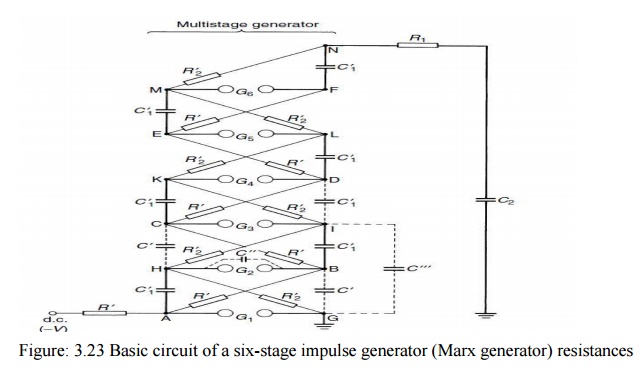
operation, a typical circuit is presented in Fig. 3.23 which shows the
connections of a six-stage generator. The dace. Voltage charges the equal stage
capacitors C01 in parallel through the high value charging resistors R0 as well
as through the discharge (and also charging).

R02 which
are much smaller than the resistors R0 and are comparable with R2 in Fig. 3.25.
At the end of the relatively long charging period(typically several seconds up
to 1 minute), the points A, B, . . . ,F will be at the potential of the dace.
source, e.g. _V with respect to earth, and the pointsG,H,, N will remain at the
earth potential, as the voltage drop during charging across the resistors R02is
negligible. The discharge or firing of the generator is initiated by the
breakdown of the lowest gap G1 which is followed by a nearly simultaneous
breakdown of all the remaining gaps. According to the traditional theory, which
does not take into account the stray capacitances Indicated by the dotted
lines, this rapid breakdown would be caused by high over voltages across the
second and further gaps: when the first gap fires, the potential at point A
changes rapidly from _V to zero, and thus the point H increases its potential
to CV.
As the
point B still would remain at the charging potential, _V, thus a voltage of 2V
would appear across G2. This high overvoltage would therefore cause this gap to
break down and the potential at point I would rise to C2V, creating a potential
difference of 3V across gapG3, if again the potential at point C would remain
at the charging potential.
This
traditional interpretation, however, is wrong, since the potentials B and C can
– neglecting stray capacitances – also follow the adjacent potentials of the
points A and B, as the resistors R0 are between. We may only see up to now that
this circuit will give an output voltage with a polarity opposite to that of
the charging voltage. In practice, it has been noted that the gap G2 must be
set to a gap distance only slightly greater than that at which G1 breaks down;
otherwise it does not operate.
According
to Edwards, Husbands and Perry_31_ for an adequate explanation one may assume
the stray capacitances C0, C00 and C000 within the circuit. The capacitances C0
are formed by the electrical field between adjacent stages; C000 has a similar
meaning across two stages. C00 is the capacitance of the spark gaps. If we
assume now the resistors as open circuits, we may easily see that the potential
at point B is more or less fixed by the relative magnitudes of the stray
capacitances. Neglecting C0 between the points Hand C and taking into account
that the discharge capacitors C01 are large in comparison to the stray capacitances,
point B can be assumed as mid-point of a capacitor voltage divider formed by
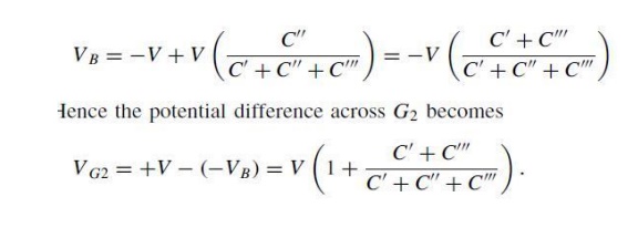
C00 and C0/C000. Thus the voltage rise of point A from _V to zero will cause
the potential B to rise from V to a voltage of

If C00
equals zero, the voltage across G2 will reach its maximum value 2V.This gap
capacitance, however, cannot be avoided. If the stage capacitancesC0 and C000
are both zero, VG2 will equal V, and a sparking of G2 would not be possible. It
is apparent, therefore, that these stray capacitances enhance favorable
conditions for the operation of the generator. In reality, the conditions set
by the above equations are approximate only and are, of course, transient, as
the stray capacitances start to discharge via the resistors. As the values of
C0 to C000 are normally in the order of some 10 pF only, the time constants for
this discharge may be as low as 10_7 to 10_8 sec. Thus the voltage across G2
appears for a short time and leads to breakdown within several tens of
nanoseconds. Transient over voltages appear across the further gaps, enhanced
also by the fact that the output terminal N remains at zero potential mainly,
and therefore additional voltages are built up across the resistor R02. So the
breakdown continues and finally the terminal N attains a voltage of C6V, or nV,
if n stages are present.
The
processes associated with the firing of such generators are even more
sophisticated. They have been thoroughly analyzed and investigated
experimentally.31,36,37_In practice for a consistent operation it is necessary
to set the distance for the first gap G1 only slightly below the second and
further gaps for earliest breakdown. It is also necessary to have the axes of
the gaps in one vertical plane so that the ultraviolet illumination from the
spark in the first gap irradiates the other gaps. This ensures a supply of
electrons released from the gap to initiate breakdown during the short period
when the gaps are subjected to the overvoltage.
If the
first gap is not electronically triggered, the consistency of its firing and
stability of breakdown and therefore output voltage is improved by providing
ultraviolet illumination for the first gap. These remarks indicate only a small
part of the problems involved with the construction of spark gaps and the
layout of the generator. Before some of these additional problems are treated,
we shall treat more realistic Marx circuits as used for the explanations so
far.
In Fig.
3.24, the wave front control resistor R1 is placed between the generator and the
load only. Such a single ‘external’ front resistor, however, has to withstand
for a short time the full rated voltage and therefore is inconveniently long or
may occupy much space. This disadvantage can be avoided if either a part of
this resistance is distributed or if it is completely distributed within the
generator. Such an arrangement is illustrated in Fig. 2.30, in which in
addition the series connection of the capacitors C01 and gaps (as proposed
originally byGoodlet_38_) is changed to an equivalent arrangement for which the
polarity of the output voltage is the same as the charging voltage. The
charging resistorsR0 are always large compared with the distributed resistors
R01and R02, andR02is made as small as is necessary to give the required time to
halve-valueT2. Adding the external front resistor R001 helps to damp
oscillations otherwise

R02:
discharge resistors. R01: internal front resistors. R001: external front
resistorexcited by the inductance and capacitance of the external leads between
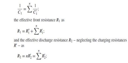
the generator and the load, if these leads are long. If the generator has
fired, the total is charge capacitance C1 maybe calculated as where n is the
number of stages. The consistent firing of such circuits could be explained as
for the generator

of Fig.
3.24. For both generator circuits, the firing is aggravated if the
resistancesR02 have relatively low values. According to equations such low
values appear with generators of high energy content and/or short times to
half-value, T2. Then the time constant for discharging the stray capacitances
to ground C000 (Fig. 3.24) will be too low and accordingly the overvoltage for
triggering the upper stages too short. By additional means providing high
resistance values within the firing period, this disadvantage can be avoided.
Related Topics