Chapter: High Voltage Engineering : Generation of High Voltages and High Currents
Series Resonant Circuit - Generation of High Voltages and Currents
Series Resonant Circuit
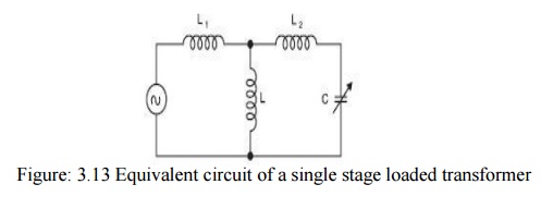
The
equivalent circuit of a single-stage-test transformer along with its capacitive
load is shown in Fig.3.14. Here L1
represents the inductance of the voltage regulator and the transformer primary,
L the exciting inductance of the
transformer, L2 the
inductance of the transformer secondary and C
the capacitance of the load. Normally inductance L is very large as compared to L1
and L2 and hence its
shunting effect can be neglected. Usually the load capacitance is variable and
it is possible that for certain loading, resonance may occur in the circuit
suddenly and the Current will then only be limited by the resistance of the
circuit and the voltage across the test specimen may go up as high as 20 to 40
times the desired value. Similarly, presence of harmonics due to saturation of
iron core of transformer may also result in resonance. Third harmonic
frequencies have been found to be quite disastrous. With series resonance, the
resonance is controlled at fundamental frequency and hence no unwanted
resonance occurs.
The
development of series resonance circuit for testing purpose has been very
widely welcome by the cable industry as they faced resonance problem with test
transformer while testing short lengths of cables. In the initial stages, it
was difficult to manufacture continuously variable high voltage and high value
reactors to be used in the series circuit and therefore, indirect methods to
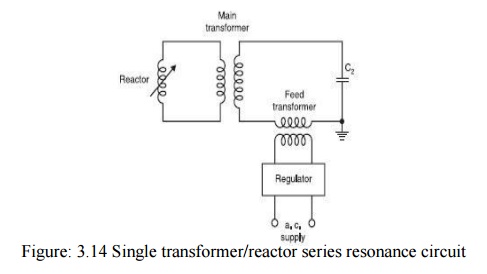
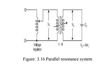
achieve this objective were employed. Fig. 3.15 shows a continuously variable
reactor connected in the low voltage winding of the step up transformer whose
secondary is rated for the full test voltage. C2 represents the load capacitance. If N is the transformation ratio and L is the inductance on the low voltage
side of the transformer, then it is reflected with N2 L value on
the secondary side (load side) of the transformer. For certain setting of the
reactor, the inductive reactance may equal the capacitive reactance of the
circuit, hence resonance will take place.
Thus, the
reactive power requirement of the supply becomes zero and it has to supply only
the losses of the circuit. However, the transformer has to carry the full load
current on the high voltage side. This is a disadvantage of the method. The
inductor are designed for high quality factors Q = ωL / R. The feed
transformer, therefore, injects the losses of the circuit only. It has now been
possible to manufacture high voltage continuously variable reactors 300 kV per
unit using a new technique with split iron core. With this, the testing step up
transformer can be omitted as shown in Fig. 3.15. The inductance of these
inductors can be varied over a wide range depend upon the capacitance of the
load to produce resonance. Here R is usually of low value. After the resonance
condition is achieved, the output voltage can be increased by increasing the
input voltage. The feed transformers are rated for nominal current ratings of
the reactor
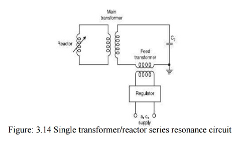
Figure:
3.15 (a) Series resonance circuit with variable h.t. reactors (b) Equivalent
circuit of (a)Figure. 3.15 (b) represents an equivalent circuit for series
resonance circuit.
Fig. 3.15
(b) represents an equivalent circuit for series resonance circuit. Here R is
usually of low value. After the resonance condition is achieved, the output
voltage can be increased by increasing the input voltage. The feed transformers
are rated for nominal current ratings of the reactor. Under resonance, the
output voltage will be
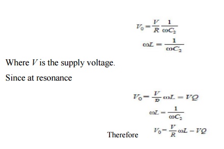
Where Q
is the quality factor of the inductor which usually varies between 40 and 80.
This means that with Q = 40, the output voltage is 40 times the supply voltage.
It also means that the reactive power requirements of the load capacitance in
kVA are 40 times the power to be provided by the feed transformer in KW. This
results in a relatively small power rating for the feed transformer.
The
following are the advantages of series resonance circuit.
·
The power requirements in KW of the feed circuit
are (kVA)/Q where kVA is the reactive
·
Power requirements of the load and Q is the quality
factor of variable reactor usually greaterthan 40. Hence, the requirement is
very small. ![]()
·
The series resonance circuit suppresses harmonics
and interference to a large extent. The near sinusoidal wave helps accurate
partial discharge of measurements and is also desirable for measuring loss
angle and capacitance of insulating materials using Schering Bridge. In case of
a flashover or breakdown of a test specimen during testing on high voltage
side, the resonant circuit is detuned and the test voltage collapses
immediately. The short circuit
·
Current is limited by the reactance of the variable
reactor. It has proved to be of great value as the weak part of the isolation
of the specimen does not get destroyed. In fact, since the arc flash over has
very small energy, it is easier to observe where exactly the flashover is
occurring by delaying the tripping of supply and allowing the recurrence of
flashover.
• No separate compensating reactors (just as we have in case of test transformers) are required. This results in a lower overall weight.
• When testing SF6 switchgear, multiple breakdowns do not result in high transients. Hence, no special protection against transients is required.
• Series or parallel connections of several units are not at all a problem. Any number of units can be connected in series without bothering for the impedance problem which is very severely associated with a cascaded test transformer. In case the test specimen requires large current for testing, units may be connected in parallel without any problem.
In an
attempt to take advantage of both the methods of connections, i.e., series and
parallel resonant systems, a third system employing series parallel connections
was tried. This is basically a modification of a series resonant system to
provide most of the characteristics of the parallel system. Fig. 3.17. Shows a
schematic of a typical series parallel method.
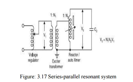
Here the
output voltage is achieved by auto transformer action and parallel compensation
is achieved by the connection of the reactor. It has been observed that during
the process of tuning for most of the loads, there is a certain gap opening
that will result in the parallel connected test system going into uncontrolled
over voltage of the test sample and if the test set is allowed to operate for a
long time, excessive heating and damage to the reactor would result. Also, it
has been observed experimentally that complete balance of ampere turns takes
place when the system operates under parallel resonance condition.
Under all
other settings of the variable reactor, an unbalance in the ampere turns will
force large leakage flux into the surrounding metallic tank and clamping
structure which will cause large circulating currents resulting in hot spots
which will affect adversely the dielectric strength of oil in the tank.
In view
of the above considerations, it has been recommended not to go in for
series-parallel resonant mode of operation for testing purpose. If a single
stage system up to 300 kV using the resonance test voltage is required,
parallel resonant system must be adopted. For test voltage exceeding 300 kV,
the series resonant method is strongly recommended. The specific weight of a
cascaded test transformer varies between 10 and 20 kg/kava where as for a
series resonant circuit with variable high voltage reactors it lies between 3
and 6 kg/kava. circuit with variable frequency sources With the development of
static frequency convertor, it has now been possible to reduce the specific
weight still further. In order to obtain resonance in the circuit a choke of
constant magnitude can be used and as the load capacitance changes the source
frequency should be changed.
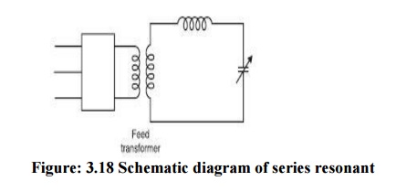
Fig. 3.18
shows a schematic diagram of a series resonant circuit with variable frequency
source. The frequency convertor supplies the losses of the testing circuit only
which are usually of the order of 3% of the reactive power of the load
capacitor as the chokes can be designed for very high quality factors.
A word of
caution is very important, here in regard to testing of test specimen having
large capacitance. With a fixed reactance, the frequency for resonance will be
small as compared to normal frequency. If the voltage applied is taken as the
normal voltage the core of the feed transformer will get saturated as V/f then
becomes large and the flux in the core will be large. So, a suitable voltage
must be applied to avoid this situation with the static frequency convertor
circuits the specific weight has come down to 0.5 kg/kVA. It is to be noted
that whereas the series resonant systems are quite popular for testing cables
and highly loss free capacitive loads, cascaded transformers are more common in
high voltage laboratories for testing equipment in MV range and also for
relatively high loads.
Related Topics