Chapter: Special Electrical Machines : Switched Reluctance Motor
Torque-Speed Characteristics of SRM(Switched Reluctance Motor)
TORQUE-SPEED CHARACTERISTICS
Torque
developed (i.e.) average torque developed but SRM depends upon the current wave
form of SRM phase winding. Current waveform depends upon the conduction period
and chopping details. It also depends upon the speed.
Consider
a case that conduction angle ϴ is
constant and the chopper duty cycle is 1.(i.e.) it conducts continuously. For
low speed operating condition, the current is assumed to be almost flat shaped.
Therefore the developed torque is constant. For high speed operating condition,
the current wave form gets changed and the average torque developed gets
reduced.
Fig.
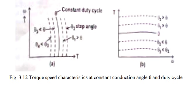
3.12(a) represents the speed torque characteristics of SRM for constant ϴ and duty cycle. It is constant
at low speeds and slightly droops as speed increases. For various other constant
value of ϴ , the
family of curves for the same duty cycle is shown in fig.3.12.

Torque
speed characteristics for fixed ϴ and for
various duty cycles are shown in fig. 3.12. ϴ and duty
cycle are varied by suitably operating the semiconductor devices.
1. Torque Speed Capability Curve
Maximum
torque developed in a motor and the maximum power that can be transferred are
usually restricted by the mechanical subsystem design parameters.
For given
conduction angle the torque can be varied by varying the duty cycle of the
chopper. However the maximum torque developed is restricted to definite value
based on mechanical consideration.

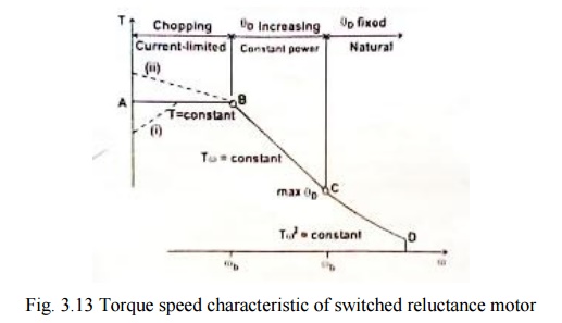
AB in the
fig.3.13 represents constant maximum torque region of operation.
At very
low speeds, the torque / speed capability curve may deviate from the clock
torque characteristics. If the chopping frequency is limited or if the
bandwidth of the current regulator is limited, it is difficult to limit the
current without the help of self emf of the motor and the current reference may
have to be reduced.
If very
low windage and core loss permit the chopper losses to be increased, so that
with higher current a higher torque is obtained. Under intermittent condition
of course very much higher torque can be obtained in any part of the speed
range up to Ѡ b.
The motor
current limits the torque below base speed. The ‗corner point‘ or base speed ‗Ѡ b‘ is
the highest speed at which maximum current can be supplied at rated voltage
with fixed firing angles. If these angles are still kept fixed, the maximum
torque at rated voltage decreases with speed squared. But if the conduction
angle is increased,(i.e.)ϴ on is
decreased, there is a considerable speed range over which maximum current can
be still be forced into the motor. This maintains the torque at a higher level
to maintain constant power characteristic. But the core losses and windage
losses increases with the speed. Thus the curve BC represents the maximum
permissible torque at each speed without exceeding the maximum permissible
power transferred. This region is obtained by varying ϴ D to its maximum value ϴ D max. ϴ D is dwell angle of the main
switching devices in each phase. Point C corresponds to maximum permissible
power; maximum permissible conduction angle
ϴ D max and duty cycle of the
chopper is unity.
Curve CD
represents TѠ 2 constant. The conduction angle is kept maximum and duty
cycle is maximum by maintaining TѠ 2 constant. D
corresponds to maximum Ѡ permissible.
The
region between the curve ABCD and X axis is the ―permissible region of
operation of SRM‖.
Related Topics