Chapter: Special Electrical Machines : Switched Reluctance Motor
Power Semiconductor Switching Circuits for SRM(Power Controllers)
POWER SEMICONDUCTOR SWITCHING
CIRCUITS FOR SRM (POWER CONTROLLERS)
The
selection of controller (converter) depends upon the application. One of the
main aspects of the research in SRM drives has been the converter design. The
main objectives of the design of the converter are performance of the drive and
cost of the drive.
The power
semiconductor switching circuits used are
1. Two power
semiconductor switching devices per phase and two diodes.
2. (n+1)
power semiconductor switching devices (n+1) diodes.
3. Phase
winding using bifilar wires.
4. Split-link
circuit used with even-phase number.
5. C-dump
circuit.
1. Two Power Semiconductor
Switching Devices per phase and two diodes
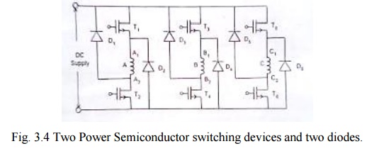
As shown
in fig 3.4 phase winding A is connected to the dc supply through power
semiconductor devices T1 and T2. Depending upon the rotor
position, when the phase winding A is to be energized the devices T1
and T2 are turned ON. When the phase winding is to be disconnected
from the supply (this instant is also dependent on the position of the shaft)
the devices T1 and T2 are turned off .The stored energy
in the phase winding A tends to maintain the current in the same direction.
This current passes from the winding through D1 and D2 to
the supply. Thus the stored energy is fed back to the mains.
Similarly
phase winding B & C are also switched on to the supply and switched off
from the supply in a cyclic manner. This circuit requires 2 power switching
devices and 2 diodes for each phase winding. For high speed operation it is
required to see that the stored energy can be fed back to the mains within the available
period.
Usually
the upper devices T1, T3 and T5 are turned on
and off from the signals obtained from the rotor position sensor .The duration
of conduction or angle of conduction θ can be controlled by using suitable
control circuitry .The lower devices T2, T4, T6
are controlled from signals obtained by chopping frequency signal. The current
in the phase winding is the result of logical AND ing of the rotor position
sensor and chopping frequency .As a result it is possible to vary the effective
phase current from a very low value to a high value .For varying the following
methods are available.
1. By
varying the duty cycle of the chopper.
2. By
varying the conduction angle of the devices.
Merits
v Control
of each phase is completely independent of the other phase.
v The
converter is able to free wheel during the chopping period at low speeds which
helps to reduce the reduce the switching frequency and thus the switching
losses of the converter.
v The
energy from the off going phase is feedback to the source, which results in
utilization of energy
Demerits
v Higher
number of switches required in each phase, which makes the converter expensive
and also used for low voltage applications.
2. (n+1) power switching devices
and (n+1) diodes
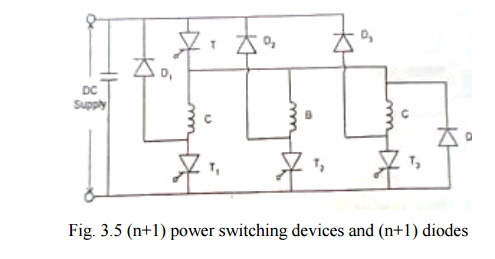
This circuit
makes use of less number of power switching devices and diodes as shown in fig
3.5. When the (SCRs) switching devices T and T1 are turned on phase
winding A is energized from the dc supply. When these devices are turned off
the stored energy in the phase winding is fed back to the mains through diodes
D and D1. When devices T and T2 are turned on the phase winding B is
energized .When they are turned off ,the stored energy in B phase winding C is
switched on and off from the mains. The cycle gets repeated.
This
circuit makes use of (n+1) power switching devices and (n+1) diodes where n is
equal to the number of phases.
Merits
v The
converter uses low number of switching devices, which reduces the cost of the
converter.
v The
converter is able to freewheel during the chopping, thus reducing the switching
frequency and losses.
v Voltage
rating of all the switching devices and the diodes are V dc, which
is relatively low.
v The
energy for the off going phase is transferred back into the source, which results
in useful utilization of the energy and also improves the efficiency.
Demerits
v Disability
to magnetize a phase while the off going phase is still demagnetizing which
results in higher torque ripple during commutation.
v At higher
speeds of the off going phase cannot be de-energized fast enough because the
common switch ―T‖ keeps turnings on intermediately, disabling forced
demagnetization.
v The
common switch conducts for all the phases and thus has higher switching stress.
3. Phase winding using bifilar
wires
Each
phase winding has two exactly similar phase windings as shown in fig 3.6.For
this bifilar wires are used .Each phase consists of two identical windings and
are magnetically coupled when one of them are excited.
In
stepper motor, the purpose of bifilar winding is for bipolar excitation with a
reduced number of switching elements.
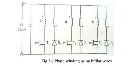
When T1
is turned on the dc current passes through the phase winding A. when the
devices T1 is turned off the stored energy in the magnetic field is
fed back to the dc source through the winding A‘ and D1 to the
supply.
The three
devices operate in a sequential way depending upon the signals obtained from
the rotor position sensor and the chopping signals for PWM technique obtained
from the controller.
Merits
v The
converter uses lower number of switching devices thus reducing the cost on the
converter.
v The
converter allows fast demagnetization of phases during commutation.
Demerits
v Bifilar
winding suffers from double number of connections.
v A poor
utilization of copper.
v Freewheeling
is not possible during chopping as the phases have -Vdc. this causes
of higher ripples in current and torque during chopping.
v The
imperfection in the coupling between the two winding causes voltage spikes
during turn off.
v The
copper loss associated with the auxiliary winding is unacceptable high for many
applications.
4. Split – link circuit used with even phase number
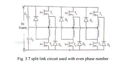
The
circuit shown in fig.3.7 is used in a range of highly efficient drives (from
4-80kw).
The main
power supply is split into two halves using split capacitors. During
conduction, energy is supplied to the phases by one half the power supply.
During commutation period, the phases demagnetize into other half of the power
supply.
When
switch T1 is turned on, phase winding 1 is energized by capacitor c1. When
switch T2 is turned off, the stored energy in the phase winding 1 is fed back
to the capacitor c2 through diode D4.
When T4
is turned on by capacitor C2 and phase winding 4 is energized. When switch T4
is turned off, stored energy in the winding 4 is feedback to the capacitor C1
through diode D1. The similar operation takes place in the remaining winding
also.
Merits
v It
requires lower number of switching devices.
v Faster
demagnetization of phases during commutation.
Demerits
v During
chopping, freewheeling is not possible as the phaser have the voltage Vdc/2. This causes higher switching
frequency and more losses.
v This is
not feasible for low voltage application.
v The
converter is fewer faults tolerant as fault in any phase will unbalance the
other phase that is connected to it.
5. C-Dump circuit
In the C
dump circuit shown in fig. 3.8. the device count is reduced to ‗n‘ plus one
additional devices to bleed the stored energy from the dump capacitor C back to
supply via the step down chopper circuit. The mean capacitor voltage is
maintained well above the supply to permit rapid defluxing after commutation.
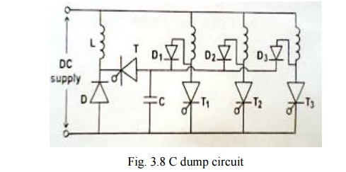
A control
failure in the energy-recovery circuit would result in the rapid build-up of
charge on the capacitor and if protective measures were not taken the entire
converter could fail from over voltage.
Demerits
v Dump
capacitor voltage is maintained ―2 Vdc‖ to allow fast demagnetization. But use
of a capacitor and an inductor in the dump circuit and also the voltage rating
of other devices is twice the bus voltage
v Monitoring
of the dump capacitor voltage 'C‘ and control of dump switch T makes the
converter very complicated and also the converter does not allow freewheeling.
Related Topics