Chapter: Special Electrical Machines : Switched Reluctance Motor
Construction and operation of SRM(Switched Reluctance Motor)
CONSTRUCTION AND OPERATION OF SRM
1. Construction of SRM
Construction
details of switched reluctance motor with six stator poles and four rotor poles
can be explained by referring to figure 3.1
The
stator is made up of silicon steel stampings with inward projected poles. The
number of poles. The number of poles of the stator can be either an even number
or an odd number. Most of the motors available have even number of stator poles
(6 or 8). All these poles carry field coils. The field coils of opposite poles
are connected in series such that their mmf‘s are additive and they are called
phase windings. Individual coil or a group of coils constitute phase windings.
Each of the phase windings are connected to the terminal of the motor. These
terminals are suitably connected to the output terminals of a power
semiconductor switching circuitry, whose input is a d.c. supply.
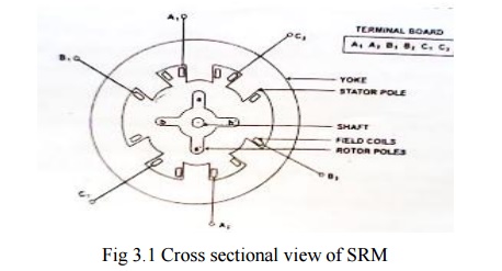
The rotor
is also made up of silicon steel stampingswith outward projected poles. Number
of poles of rotor is different from the number of poles of the stator. In most
of the avaliable motors the number of poles of the rotor is 4 or 6 depending
upon the number of stator poles 6 or 8.
The rotor
shaft carries a position sensor. The turning ON and turning OFFoperation of the
various devices of the power semiconductor circuitry are influenced by the
signals obtained from the rotor position sensor.
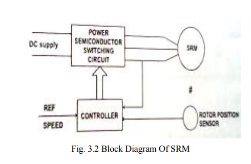
2. Block Diagram Of SRM
Fig. 3.2
shows the block diagram of SRM. Dc supply is given to the power semiconductor
switching circuitry which is connected to various phase windings of SRM. Rotor
position sensor which is mounted on the shaft of SRM, provides signals to the
controller about the position of the rotor with reference to reference axis.
Controller collects this information and also the reference speed signal and
suitably turns ON and OFF the concerned power semiconductor device to the dc
supply. The current signal is also fed back to the controller to limit the
current within permissible limits.
3. Principle of operation
Fig. 3.3
represents the physical location of the axis stator poles and rotor poles of a
6/4 SRM.
To start
with stator pole axis AA‘ and rotor pole axis aa‘ are in alignment as shown in
fig. 3.3(a). They are in the minimum reluctance position so far as phase
windings is concerned. Then dLa/dθ=0.
At this position inductance of B windings is neither maximum nor minimum. There
exists dLb/dθ and dLc/dθ.
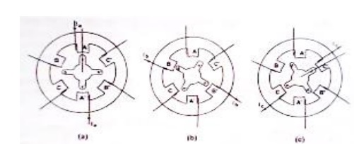
Now if B
phase is energized then the rotor develops a torque because of variable
reluctance and existences of variation in inductance. The torque developed is
equal to (1/2)iB2(dLB/dθ). This direction is such that
BB‘ and bb‘ try to get aligned. If this torque is more than the opposing load
torque and frictional torque the rotor starts rotating. When the shaft occupies
the position such that BB‘ and bb‘ are in alignment (i.e.,) θ=30°, no torque is
developed as in this position dLB/dθ=0. [Vide fig. 3.3(b)]
Now phase
winding B is switched off and phase winding C is turned on to DC supply. Then
the rotor experiences a torque as (dLC/dθ) exists. The rotor
continues to rotate. When the rotor rotates further 30°, the torque developed
due to winding C is zero [vide fig. 3.3(c)] Then the phase winding C is
switched off and phase winding A is energized. Then rotor experiences a torque
and rotates further step 30°. This is a continuous and cyclic process. Thus the
rotor starts. It is a self-starting motor.
As the
speed increases, the load torque requirement also changes. When the average
developed torque is more than the load torque the rotor accelerates. When the
torques balance the rotor attains dynamic equilibrium position. Thus the motor
attains a steady speed. At this steady state condition power drawn from the
mains is equal to the time rate of change of stored energy in magnetic circuit
and the mechanical power developed.
When the
load torque is increased, the speed of the motor tends to fall, so that the
power balance is maintained. If the speed is to be develop at the same value,
the develop torque is to be increased by increasing the current. Thus more
power is drawn from the mains. Vice-versa takes place when the load is reduced.
Thus electrical to mechanical power conversion takes place.
Related Topics