Chapter: Electric Energy Generation and Utilisation and Conservation : Wind Energy
Structure and components of wind mill
Structure and
components of wind mill
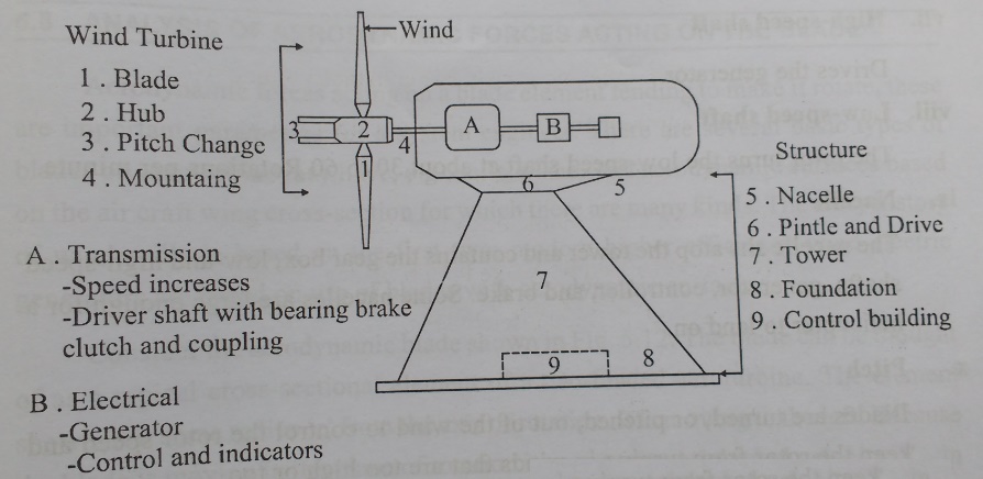
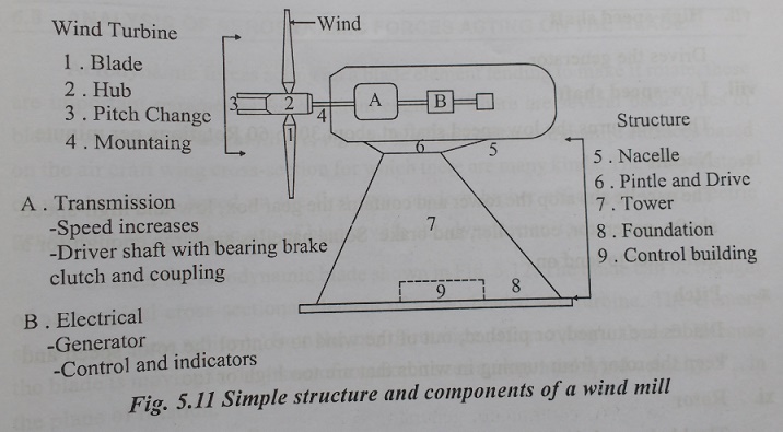
The
simple structure of horizontal axis wind turbine (wind mill) shown in fig.5.11.
The
following components are used in a wind mill.
(1) Anemometer
Measure
the wind speed and transmits wind speed data to the controller
(2) Blades
Most
turbines have either two or three blades. Wind blowing over the blades causes
the blades to “lift” and rotate.
(3) Brake
A
disc brake, which can be applied mechanically, electrically, or hydraulically
to stop the rotor in emergencies.
(4) Controller
The
controller starts up the machine at wind speeds of about 8 to 16 miles per hour
(mph) and shuts off the machine at about 55 mph. Turbines do not operate at
wind speeds above about 55 mph because they might be damaged by the high winds.
(5) Gear box
Gear
connect the low-speed shaft to the high speed shaft and increase rotational
speeds from about 30 to 60 rotations per minute (rpm) to about 1000 to 1800
rpm, the rotational speed required by most generators to produce electricity.
The gear box is a costly (and heavy) part of the wind turbine and engineers are
exploting “direct-drive” generators that operate at lower rotational speeds and
don’t need gear boxes.
(6) Generator
Usually
an off-the-shelf induction generator that produces 60-cyclic AC electricity.
(7) High
speed shaft
Drives
the generator.
(8) Low-speed
shaft
The
rotor turns the low-speed shaft 30 to 60 rotations per minute.
(9) Nacelle
The
nacelle sits the lower and contains the gear box, low-and high-speed shafts,
generator, controller, and brake. Some nacelle are large enough for a
helicopter to land on.
(10) Pitch
Blades
are turned, or pitched, out of the wind to control the rotor speed and keep the
rotor form turning in winds that are too high or too.
(11) Rotor
The
blades and the hub together are called the rotor.
(12) Tower
Towers
are made from tubular steel (shown here), concrete, or steel lattice. Because
wind speed increases with height, taller towers enable turbines to capture more
energy and generate more electricity.
(13) Wind direction
This
is an “upwind” turbine, so called because it operates facing into the wind.
Other turbines are designed to run “downwind”, facing away from the wind.
(14) Wind vane
Measure
wind direction and communicates with the yaw drive to orient the turbine
properly with respect to the wind.
(15) Yaw drive
Upwind
turbines face into the wind, the yaw drive is used to keep the rotor facing
into the wind as the wind direction changes. Downwind turbines don’t require a
yaw drive, the wind blows the rotor downwind.
(16) Yaw motor
Powers
the yaw drive.
Related Topics