Chapter: Electric Energy Generation and Utilisation and Conservation : Wind Energy
Analysis of Aerodynamic Forces Acting on the Blade

ANALYSIS OF
AERODYNAMIC FORCES ACTING ON THE BLADE
Aerodynamic
forces acting on a blade element tending to make it rotate, these are important
parameters for a system engineer. These are several basic types of blades on
aeriturbine may have, eg.,sails, planes and aerodynamic surfaces based on the
air craft wing cross-section for which there are many kinds. The early history
of wind mills is based on the first two; modern higher efficiency wind-electric
generators are based on use of blades with aerodynamic surfaces.
Consider
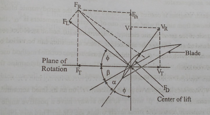
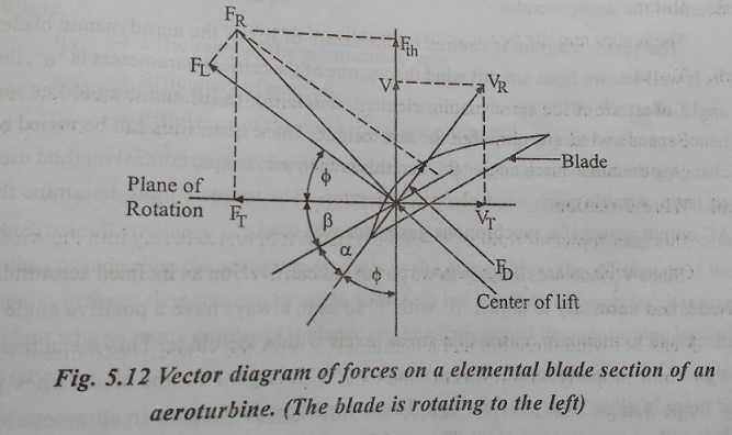
the aerodynamic blade shown in fig.,5.12. The blade can be through of as a
typical cross-sectional element of a two-bladed aeroturbine . The element shown
is at some radius ‘r’ from the axis of rotation. It is moving to the left.
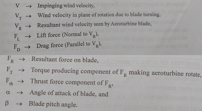
Because the blade is moving in the plane of rotation it sees a tangential wind
velocity, VT, in the plane of rotation.


This
component added vectorially to the impinging wind velocity gives the resulting
wind velocity, VR, seen by the rotating balde element. At right
angles to VR, is the lift force FL, caused by the
aerodynamic shape of the blade. The drag force, FD is parallel to VR.
The vector sum of FL and FD
is FR which has a torque producing component, FT and a
thrust producing component. The former is what drives the aero-turbine
rotationally and the later tends to flex and also overturn the aerogenerator.
The
vector diagram is centred on the centre of lift of the aerodynamic blade. As is
well known from aircraft wind theory, one of the critical parameters is ’a’
the angle of attack of the aerodynamic element, It determines lift and drag
forces and hence speed and torque output of the aeroturbine. This quantities
can be varied by changing the blade pitch angle ‘β’, and this is the basis
torque control method used on large variable pitch wind-electric generators.
The torque whould determine the AC output power if a synchronous generator was
used.
Since
VT, increases linearly as we go out radically, ‘r’, on an inclined
aeroturbine blade, it is necessary to adjust ‘β’ with ‘r’ so as to always have
a positive angle of attack and to maintain reasonable stress levels within the
blade. This mean that at large ‘r’, ‘β’ is made small while at small ‘r’, ’β’
is large. Thus the blade ‘bites’ the air more in close than near the tips.
These the considerations result in an aeroturbine blade with an apparent twist
in it. The need for twisting wind mills sails was recognised hundreds of years
ago and widely used on Dutch wind mill.
Having
now achieved an elementary understanding of the basics of what turns the
aeroturbine, we see that the airfoil orientation for an aeroturbine drives by
the wind is exactly opposite to the orientation of a classical airplane
propeller which is mechanically driven and whose function is to go give a lift
force in the axial direction. Thus, through aircraft wing theory is applicable
to the operation of an aeroturbine, direct of a classical aircraft propeller on
an aeroturbine, would not produce the most efficient aeroturbine because the
aerodynamic surface is oriented backwards to what it should be.
Related Topics